
Left atrial appendage closure and delivery system thereof

a technology of appendage and closure, applied in the field of medical devices, can solve the problems of significant increase in morbidity and mortality, lack of closure design, and inability to completely seal off the laa orifice, and achieve the effect of better loading or discharging

Active Publication Date: 2019-04-25
SHANGHAI MICROPORT CARDIOADVENT CO LTD
View PDF0 Cites 2 Cited by
  • Summary
  • Abstract
  • Description
  • Claims
  • Application Information

AI Technical Summary

Benefits of technology

The present invention provides a system for delivering and deploying an LAA closure that is capable of better loading and deployment of the closure. The system includes a first delivery member and second delivery member that can crimp and load the closure, respectively. The closure is designed with supporting struts and rods that form a dense mesh and provide high strength, as well as prevent dislocation and damage to tissue. The system also allows for repeated relocations and easy deployment at a suitable site. Overall, the invention provides a more efficient and safe method for closing off the LAA.

Problems solved by technology

Its most significant hazard is that it promotes the formation of blood clots which, when dislodged, tend to be associated with complications that may cause a significant increase in morbidity and mortality, such as stroke and occlusion of peripheral vessels.
Anticoagulation is currently employed as a default approach for lowering the risk of stroke in AF patients, which, however, suffers from a number of limitations.
When inserted into the LAA, a closure of this design cannot completely seal off the LAA orifice due to an irregular shape of the LAA orifice and limited deformability of the closure itself, still leaving a channel for the formation of a clot in the LAA due to AF.
In addition, the LAA is a multi-lobed structure varying in shape and depth among individuals, and the closure cannot adapt to all possible LAA anatomies.
Further, it suffers from insufficient anchoring.
As a result, after the lobe is positioned inside the LAA and the disk is buckled at the LAA orifice, the disk may not satisfactorily seal the LAA orifice under traction from the lobe and may fail to achieve a desired occlusion effect.
Moreover, the lobe and the disk are both limited in lengthwise adjustability, and hence difficult to achieve a favorable anchoring and blood flow blockage effect.
Again, the disk of this design is also incapable of adapting to various possible LAA anatomies.
Furthermore, the insert plug design and the disc-like plug design both suffer from insufficient strength.

Method used


Image

  • Left atrial appendage closure and delivery system thereof
  • Left atrial appendage closure and delivery system thereof
  • Left atrial appendage closure and delivery system thereof

Examples


embodiment 1

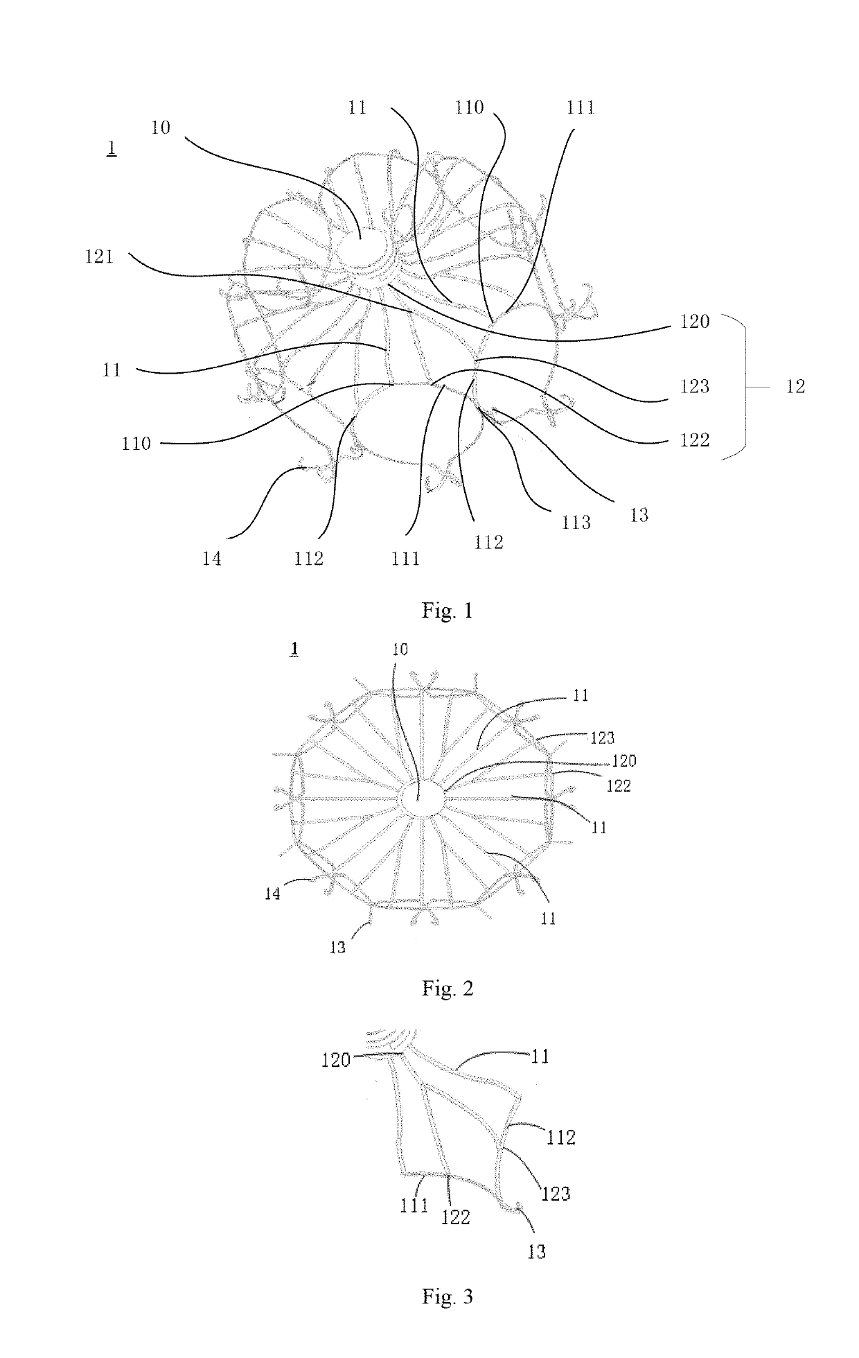
[0081]Reference is now made to FIGS. 1 to 3, in which FIG. 1 illustrates a perspective structural schematic view of a left atrial appendage (LAA) closure according to a first embodiment of the present invention, FIG. 2 illustrates a top schematic view of the LAA closure according to the first embodiment of the present invention, and FIG. 3 illustrates a partially enlarged schematic view of the LAA closure according to the first embodiment of the present invention. As shown in FIGS. 1 to 3, the LAA closure 1 includes a plurality of supporting struts 11. The supporting struts 11 are distributed around a first hub 10 and extend outwardly from the first hub 10. Each supporting strut 11 bifurcates at a first position 110 into a left branch 111 and a right branch 112. The left branch 111 of each supporting strut 11 is joined with the right branch 112 of an adjacent one of the supporting struts 11 at a second position 113. The branches further extend distally to form distal ends thereof. T...

embodiment 2

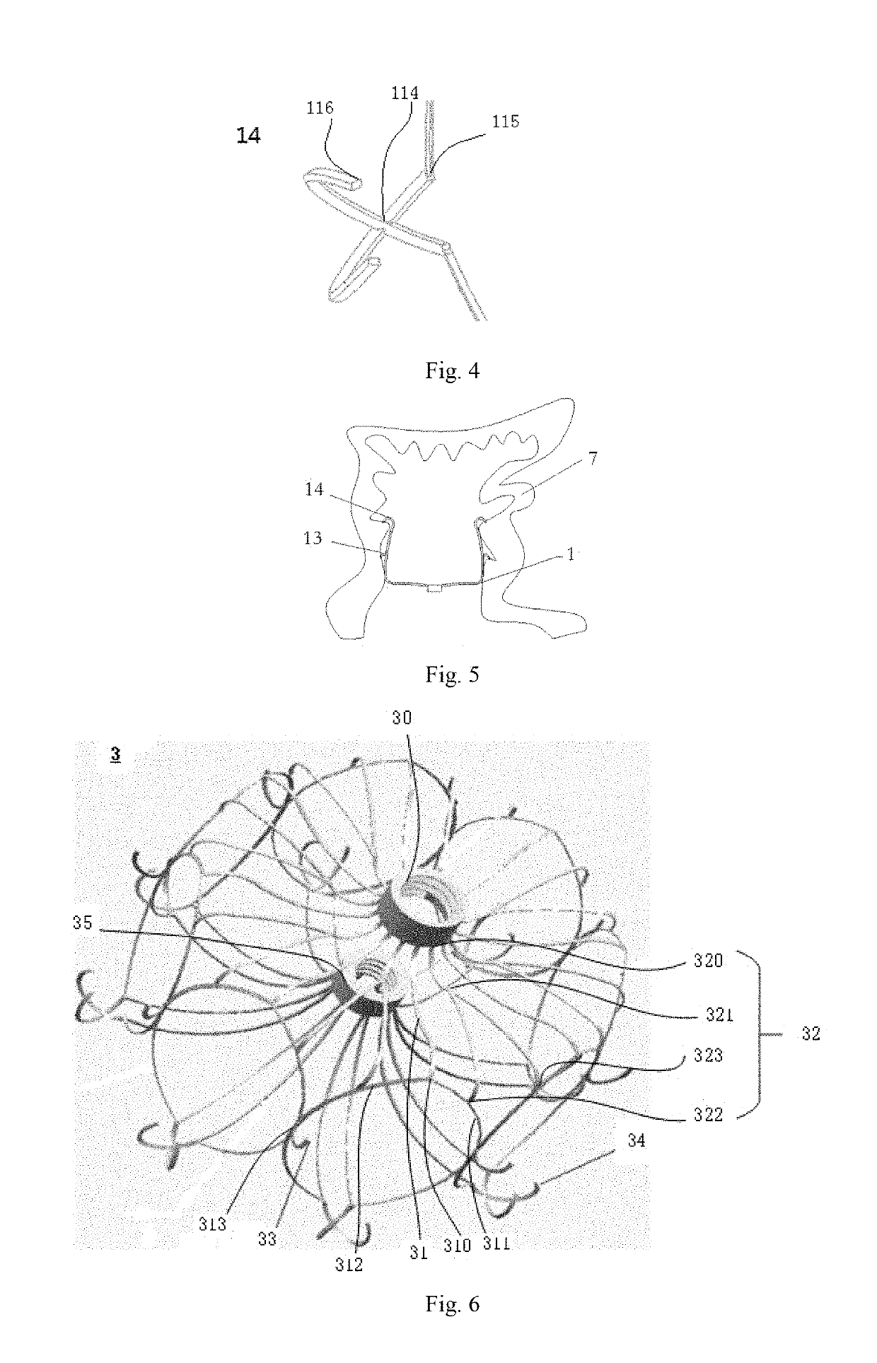
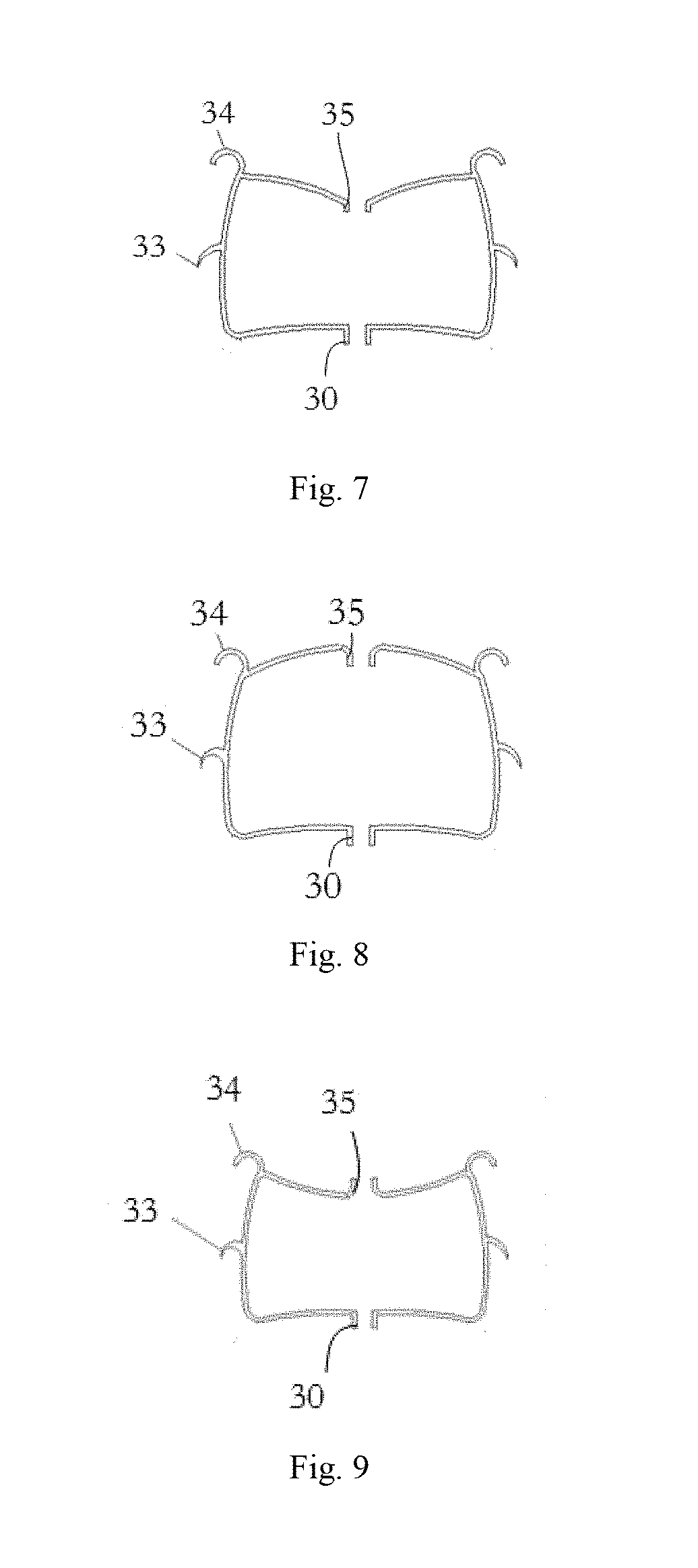
[0097]Reference is now made to FIGS. 6 and 7, in which FIG. 6 illustrates a perspective structural schematic view of an LAA closure according to a second embodiment of the present invention and FIG. 7 illustrates a cutaway schematic view of the LAA closure according to the second embodiment of the present invention. As shown in FIGS. 6 and 7, the LAA closure 3 includes a plurality of supporting struts 31. The supporting struts 31 are distributed around a first hub 30 and extend outwardly from the first hub 30. Each supporting strut 31 bifurcates at a first position 310 into a left branch 311 and a right branch 312. The left branch 311 of each supporting strut 31 is joined with the right branch 312 of an adjacent one of the supporting struts 31 at a second position 313. The branches further extend distally to form distal ends thereof. The LAA closure 3 further includes supporting rods 32 each interposed between corresponding adjacent two of the supporting struts 31.

[0098]Additionally...

embodiment 3

[0105]FIG. 10 is a perspective structural schematic view of an LAA closure according to a third embodiment of the present invention. As shown in FIG. 10, the LAA closure 4 includes a plurality of supporting struts 41. The supporting struts 41 are distributed around a first hub 40 and extend outwardly from the first hub 40. Each supporting strut 41 bifurcates at a first position 410 into a left branch 411 and a right branch 412. The left branch 411 of each supporting strut 41 is joined with the right branch 412 of an adjacent one of the supporting struts 41 at a second position 413. The branches further extend distally to form distal ends thereof. The LAA closure 4 further includes supporting rods 42 each interposed between corresponding adjacent two of the supporting struts 41. Extensions projecting inwardly from the distal ends terminate at a second hub 45.

[0106]In addition, each supporting rod 42 has a first end 420 connected to an outer side of the first hub 40. Each supporting r...


PUM


Abstract

A left atrial appendage (LAA) closure (1) and a system (6) for delivering the LAA closure are disclosed. The LAA closure (1) includes supporting struts (11), wherein the supporting struts (11) are distributed peripherally around a first hub (10) and extend outward, the supporting strut (11) bifurcates at a first position (110) into a left branch (111) and a right branch (112). The left branch (111) of each supporting strut (11) and the right branch (112) of an adjacent supporting strut join each other at a second position (113) and extend distally to form a distal end. The LAA closure further includes a supporting rod (12) between adjacent supporting struts (11) which ensures stability, absence of irregular deformation and lateral slippage, of the LAA closure (1). With the supporting rods (12) between the adjacent supporting struts (11), the LAA closure (1) forms a dense mesh which imparts high overall strength of the LAA closure (1).

Description

TECHNICAL FIELD[0001]The present invention relates to the field of medical devices and, in particular, to a left atrial appendage (LAA) closure and a system for the delivery thereof.BACKGROUND[0002]Atrial fibrillation (AF) is the most common arrhythmia seen in clinical practice and has an estimated prevalence of 0.5-1.3% in the general population. Its most significant hazard is that it promotes the formation of blood clots which, when dislodged, tend to be associated with complications that may cause a significant increase in morbidity and mortality, such as stroke and occlusion of peripheral vessels. Stroke is the most common and harmful complication of AF, and there are about 15 million cases of stroke reported globally every year, in which 20% to 25% are attributed to AF. Studies show that 60% of rheumatic AF patients have their cardiogenic clots come from the left atrial appendage (LAA), and over 90% of non-valvular AF patients have their clots formed in the LAA. Therefore, prev...

Claims


Application Information

Patent Timeline
Patent Type & Authority Applications(United States)
IPC IPC(8): A61B17/00A61B17/12
CPCA61B17/0057A61B17/12122A61B17/12172A61B2017/00632A61B2017/00579A61B2017/12095A61B17/12A61B17/12168
Inventor WANG, ZHENZHOU, YIYAO, YAOLI, JUNFEILUO, QIYIHUANG, HAIYONG
Owner SHANGHAI MICROPORT CARDIOADVENT CO LTD
Learn More