Coolant control valve and a cooling system having same

Active Publication Date: 2019-04-25
HYUNDAI MOTOR CO LTD +1
14 Cites 3 Cited by

AI-Extracted Technical Summary

Problems solved by technology

With thick oil, friction and fuel consumption increase.
Also, the time taken for catalyst activation becomes lengthened and exhaust gas quality may be deteriorated.
When the engine coolant temperature is excessively high, knocking may occur.
If ignition timing is adjuste...

Method used

[0073]In an embodiment of the present disclosure, the failsafe valve 160 provided at the coolant control valve unit 110 improves temperature sensitivity. Accordingly, stability of t...

Benefits of technology

[0031]According to an embodiment of the present disclosure, temperature sensitivity of the fail-safe valve may be improved by forming a temperature sensing passage at the wall formed at one side of the fail-safe valve.
[0032]Also, stab...

Abstract

A coolant control valve unit includes a valve housing. The valve housing includes a first coolant supply passage and a second coolant supply passage, a coolant chamber in which coolant supplied through the first and second supply passages gathers, a first distribution passage and a second distribution passage being distributed from the coolant chamber to coolant components, and a bypass passage bypassing the first distribution passage. The coolant control valve unit also includes first and second valves disposed to open and close the first distribution passage and the second supply passage, a thermostat of a temperature sensitive type installed at the bypass and operating by a coolant temperature, a valve operator controlling movement of the first and second valves, respectively, and a wall formed at one side of the thermostat and in which a cooling passage is formed such that the coolant flows from the coolant supply passage to the second distribution passage.

Application Domain

Liquid coolingCoolant flow control +5

Technology Topic

Nuclear engineeringCoolant flow +4

Image

  • Coolant control valve and a cooling system having same
  • Coolant control valve and a cooling system having same
  • Coolant control valve and a cooling system having same

Examples

  • Experimental program(1)

Example

[0036]An embodiment of the present disclosure is hereinafter described in detail with reference to the accompanying drawings.
[0037]The size and thickness of the parts in each configuration illustrated in the drawings may be arbitrarily illustrated for explanatory convenience. However, the present disclosure is not limited thereto, and the thicknesses may be enlarged for more apparently expressing various portions and regions.
[0038]In addition, in order to more clearly explain an embodiment of the present disclosure, a detailed description of a portion, which is not related to the disclosure, may have been omitted. Also, like reference numerals designate like or similar constituent elements throughout the specification and drawings.
[0039]Names of elements in the following description may be distinguished as “first”, “second”, and the like in order to distinguish the elements because the names of the elements are the same. Those elements are not particularly limited to any specific order thereof.
[0040]The following reference numbers, names, and descriptions are used throughout the drawings and the detailed description: [0041] 100: cylinder head [0042] 105: cylinder block [0043] 110: coolant control valve unit [0044] 115: low pressure EGR cooler [0045] 120: heater [0046] 125: high pressure EGR valve [0047] 130: oil cooler [0048] 135: radiator [0049] 140: coolant pump [0050] 145: coolant temperature sensor [0051] 150: bypass valve [0052] 160: fail safe valve [0053] 162: cooling portion [0054] 164: wall [0055] 166: bypass passage [0056] 168: cooling passage [0057] 170: piston rod [0058] 200: valve housing [0059] 210a, 201b, 210c: first, second, and third valves [0060] 215a, 215b, 215c: first, second, and third rods [0061] 230: head coolant supply passage [0062] 245a, 400, 245c: first, second, and third distribution passages [0063] 245b: block coolant supply passage [0064] 270: cam [0065] 280: coolant chamber [0066] 290: elastic member
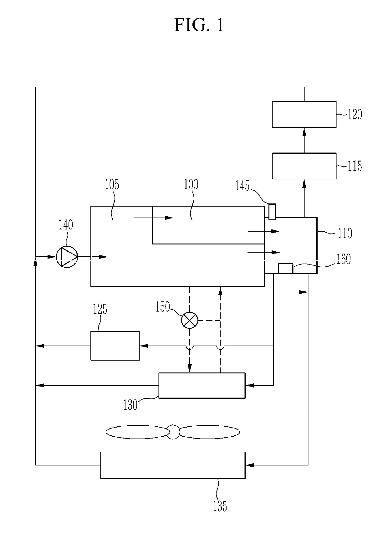
[0067]FIG. 1 is a schematic diagram illustrating an entire coolant flow in a cooling system having a coolant control valve unit according to an embodiment of the present disclosure.
[0068]Referring to FIG. 1, an engine system includes a cylinder head 100, a cylinder block 105, a coolant pump 140, a high pressure EGR valve 125, a bypass valve 150, an oil cooler 130, a radiator 135, a coolant control valve unit 110, a coolant temperature sensor 145, a low pressure EGR cooler 115, a heater 120, and a fail-safe valve 160.
[0069]The cylinder head 100 is disposed on the cylinder block 105. A combustion chamber is formed at the cylinder block 105 and intake ports and exhaust ports that are connected to the combustion chamber are formed at the cylinder head 100.
[0070]The coolant control valve unit 110 distributes coolant delivered from the cylinder head 100 and the cylinder block 105 to the low pressure EGR cooler 115, the heater 120, the radiator 135, the high pressure EGR valve 125, and the oil cooler 130.
[0071]An oil line is diverged from one side of the cylinder block 105 so that the oil is distributed to the oil cooler 130. The bypass valve 150 controls flow of the oil.
[0072]The fail-safe valve 160 bypasses overheated coolant to the radiator 135 in a state that the coolant control valve unit 110 does not operate, i.e., is fixed or stuck. Here, the fail-safe valve may have a structure of a wax type thermostat, where the thermostat has a cooling portion filled with wax. The wax contracts and expands according to a coolant temperature of the coolant to change the state of, i.e., open or close the thermostat or fail-safe valve.
[0073]In an embodiment of the present disclosure, the failsafe valve 160 provided at the coolant control valve unit 110 improves temperature sensitivity. Accordingly, stability of the coolant control valve unit and the whole cooling system may be improved in an overheated condition of the coolant in a state that the cooling control valve unit is fixed or stuck.
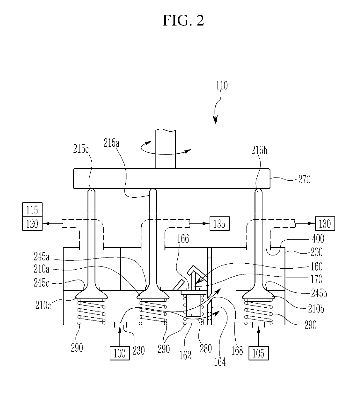
[0074]FIG. 2 is a schematic cross-sectional view of a coolant control valve unit according to an embodiment of the present disclosure.
[0075]Referring to FIG. 2, the coolant control valve unit 110 includes a cam 270, a first rod 215a, a second rod 215b, a third rod 215c, a corresponding first valve 210a, a corresponding second valve 210b, a corresponding third valve 210c, a respective elastic member 290, a valve housing 200, a head coolant supply passage 230, and a block coolant supply passage 245b.
[0076]Further, the coolant control valve unit 110 includes a first distribution passage 245a, a second distribution passage 400, a third distribution passage 245c, a wall 164, a cooling passage 168, the fail-safe valve 160, a coolant chamber 280, and a bypass passage 166. Further, the fail-safe valve 160 includes a cooling portion 162 and a piston rod 170.
[0077]A valve operator (a motor or the like, not shown) rotates the cam 270. An inclined surface set on a lower surface of the cam 270 presses the upper ends of the first, second, and third rods 215a, 215b, and 215c toward the lower portions (downward in FIG. 2). Further, the first, second, and third valves 210a, 210b, and 210c may open and close the first distribution passage 245a, the block coolant supply passage 245b, and the third distribution passage 245c, respectively.
[0078]The third valve 210c is disposed on one side of the first valve 210a and the fail-safe valve 160 is disposed at the other side of the first valve 210a. The fail-safe valve 160 opens and closes the bypass passage 166.
[0079]The cooling portion 162 is disposed at a lower portion of the fail-safe valve 160 and the piston rod is disposed at an upper portion of the fail-safe valve 160. The elastic member 290 elastically supports a valve sheet (not shown) formed on an upper end of the cooling portion 162 toward the upper portion to close the bypass passage 166.
[0080]When the cooling portion 162 is heated by the coolant temperature, the wax that fills the cooling portion 162 expands. The expanded wax moves the piston rod 170 toward the upper portion. The cooling portion 162 and the valve sheet move toward the lower portion in an opposing direction of the moving direction of the piston rod 170 such that the bypass passage 166 is opened.
[0081]In an embodiment of the present disclosure, the fail-safe valve 160 has a structure of a wax type thermostat, which structure is a known technology.
[0082]The wall 164 is oriented or formed in upper and lower directions on the other side of the fail-safe valve 160, opposite the first valve 210a. The cooling passage 168 is formed at a position corresponding to the cooling portion 162 at and through the wall 164.
[0083]At one side of the wall, the third valve 210c, the first valve 210a, and the fail-safe valve 160 are disposed in sequence. On the other side of the wall 164, the second valve 210b is disposed and the second distribution passage 400 is formed on the upper side of the second valve 210b corresponding to the second rod 215b, spaced from the block coolant supply passage 254b.
[0084]The second distribution passage 400 is connected or communicates with the oil cooler. Coolant supplied from the cylinder head 100 or the cylinder block 105 gathers in the coolant chamber 280 in the valve housing 200. The coolant gathered in the coolant chamber 280 is constantly supplied to the oil cooler 130 through the second distribution passage 400.
[0085]The head coolant supply passage 230 is formed at the one side of the wall 164 and the second distribution passage 400 is formed at the other side. The coolant supplied to the head coolant supply passage 230 passes through the cooling portion 162 of the fail-safe valve 160 and the cooling passage 168 to flow to the second distribution passage 400.
[0086]Likewise, when the second valve 210b is opened, the block coolant supply passage 245b is opened such that the coolant supplied from the cylinder block 105 may flow to the second distribution passage 400.
[0087]The first distribution passage 245a is connected with the radiator 135, the third distribution passage 245c is connected with the heater 120 and the low pressure EGR cooler 115, and the bypass passage 166 is connected with the radiator 135.
[0088]The wall 164 separates a space in which the fail-safe valve 160 is disposed and a space in which the second rod 215b is disposed. The coolant may bypass a passage (no reference numbers shown) to flow to the second distribution passage 400. As illustrated in FIG. 2, passages may be formed on an upper and lower portion of the wall 164.
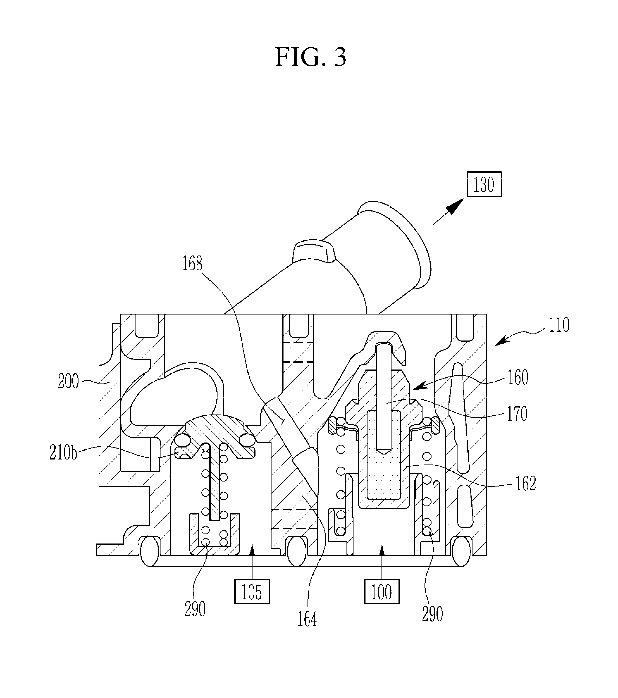
[0089]FIG. 3 is a partial cross-sectional view of a coolant control valve unit according to an embodiment of the present disclosure.
[0090]Referring to FIG. 3, the valve housing 200 is formed such that the second valve 210b and the fail-safe valve 160 are disposed in the valve housing 200. The second valve 210b is configured to open and close the block coolant supply passage 245b. The fail-safe valve 160 is configured to open and close the bypass passage 166.
[0091]With reference to FIG. 3, the wall 164 separates a region in which the second valve 210b is disposed and a region in which the fail-safe valve 160 is disposed into a right and left portion. The cooling passage 168 is formed at and through the wall 164 corresponding to the cooling portion 162 of the fail-safe valve 160. The cooling passage 168 is formed to be inclined toward an upper portion of the wall 164.
[0092]On an upper side portion of the second valve 210b, the second distribution passage 400 connected with the oil cooler 130 is formed. On a lower side portion of the fail-safe valve 160, the head coolant supply passage 230 to which the coolant supplied from cylinder head 100 is formed.
[0093]Accordingly, the coolant supplied to the head coolant supply passage 230 passes the cooling portion 162 of the fail-safe valve 160, the coolant passage 168 of the wall 164, and the second distribution passage 400 such that the coolant stably flows to the oil cooler 130.
[0094]In an embodiment of the present disclosure, the wall 164 separates both sides. The coolant supplied from the head coolant supply passage 230 may bypass the passage (no reference numbers shown) to flow toward the oil cooler 130.
[0095]Further, the coolant supplied from the cylinder block 105 to the lower portion of the second valve 210b flows toward the upper side portion through the block coolant supply passage 245b according to opening and closing operations of the second valve 210b.
[0096]Further, a portion of the coolant flowed or directed toward the upper side portion through the block coolant supply passage 245b passes the second distribution passage 400 to be supplied to the oil cooler 130. Further, the remaining coolant may pass the passage formed at the wall 164 or the cooling passage 168 and be supplied to the heater 120 or the radiator 135 through the first and third valves 210a and 210c.
[0097]In an embodiment of the present disclosure, the head coolant supply passage 230 may be referred to as the first supply passage and the block coolant supply passage 245b may be referred to as the second supply passage.
[0098]While this disclosure has been described in connection with what are presently considered to be practical embodiments, it is to be understood that the disclosure is not limited to the disclosed embodiments.

PUM

no PUM

Description & Claims & Application Information

We can also present the details of the Description, Claims and Application information to help users get a comprehensive understanding of the technical details of the patent, such as background art, summary of invention, brief description of drawings, description of embodiments, and other original content. On the other hand, users can also determine the specific scope of protection of the technology through the list of claims; as well as understand the changes in the life cycle of the technology with the presentation of the patent timeline. Login to view more.

Similar technology patents

Automatic pet feeder

ActiveUS20160007564A1improve stability
Owner:TONGFU MFG

Method for controlling transmission of sink nodes in wireless sensor network

InactiveCN101557607AImprove stabilitySend window fluctuations are less
Owner:SOUTHEAST UNIV

Coverage rate test processing method and device and coverage rate test server and system

ActiveCN103095518AImprove stabilityReduce the probability of failure
Owner:ALIBABA GRP HLDG LTD

Classification and recommendation of technical efficacy words

Why Eureka
Try Eureka