Heat exchanger made of plastic material and vehicle comprising this heat exchanger

a heat exchanger and plastic material technology, applied in indirect heat exchangers, light and heating apparatuses, laminated elements, etc., can solve the problems of relatively large bulk relatively limited efficiency, and relatively large drawback of aluminum heat exchangers, etc., to achieve improved efficiency, large space, and freedom of shap

Active Publication Date: 2019-04-25
NOVARES FRANCE
View PDF0 Cites 0 Cited by
  • Summary
  • Abstract
  • Description
  • Claims
  • Application Information

AI Technical Summary

Benefits of technology

[0031]This vehicle offers a possibility of heat exchange with an improved efficiency, a larger place available thanks to the compactness of the heat exchanger, and the freedom of shape offered by the plastic material.
[0032]The heat exchanger allows using several fluids to cool down or heat up one or several other fluid(s), which is advantageous in terms of efficiency, because depending on the operating speed of a vehicle, some fluids are more suitable for cooling or heating one or several other fluid(s).

Problems solved by technology

However, a drawback of these heat exchangers is a relatively significant bulk, in particular due to the alternation of intermediate spaces dedicated to a first fluid and of spaces dedicated to a second fluid.
In addition, the efficiency is relatively limited.
Moreover, aluminum heat exchangers are relatively bulky.
Their parallelepipedal shape is a constraint to the integration of these exchangers in a complex environment, and does not allow an optimum heat transfer efficiency of a part or a subset due to the only partial occupation by the exchanger of the volume in which it may be positioned.

Method used


Image

  • Heat exchanger made of plastic material and vehicle comprising this heat exchanger
  • Heat exchanger made of plastic material and vehicle comprising this heat exchanger
  • Heat exchanger made of plastic material and vehicle comprising this heat exchanger

Examples


Embodiment Construction

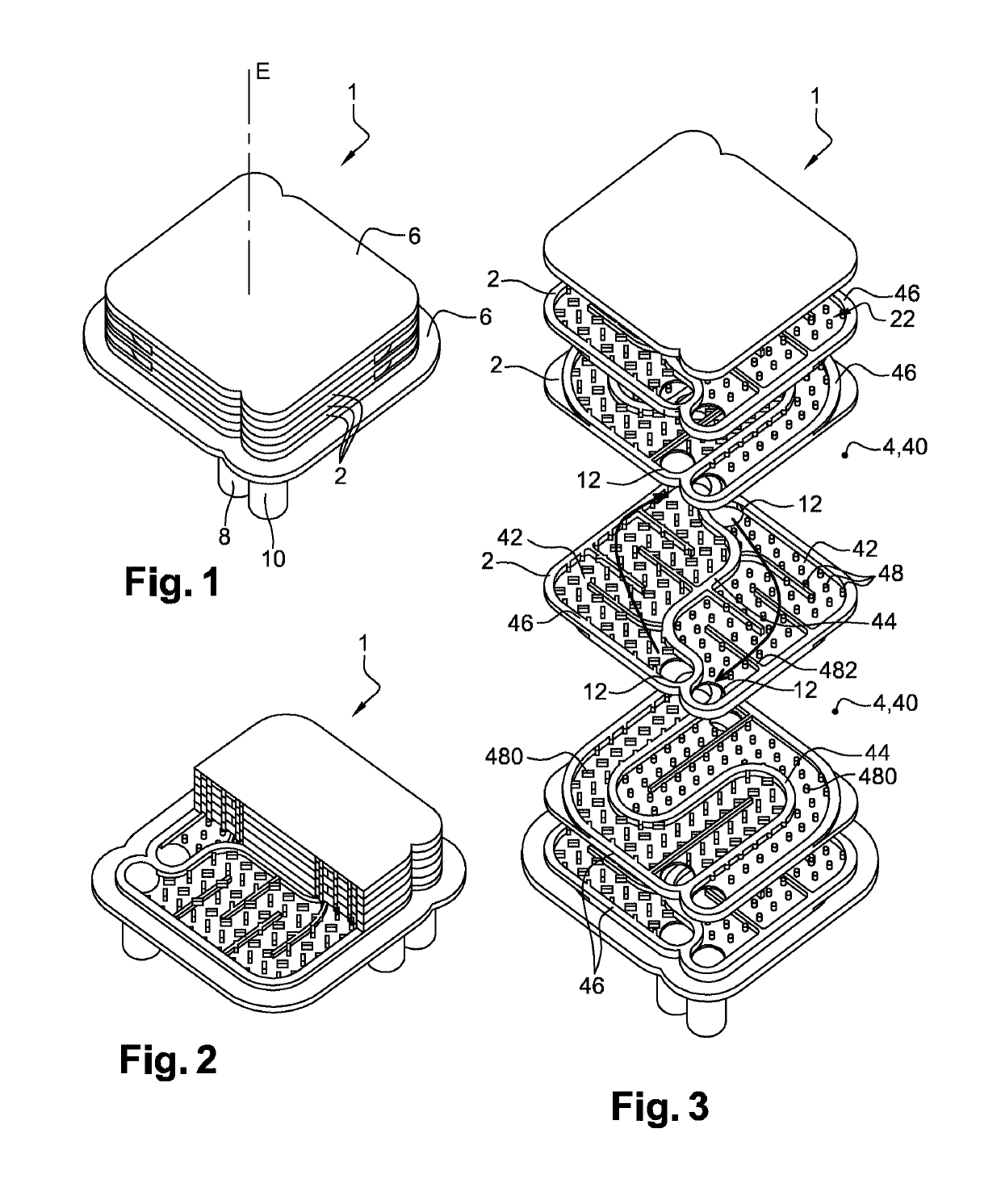
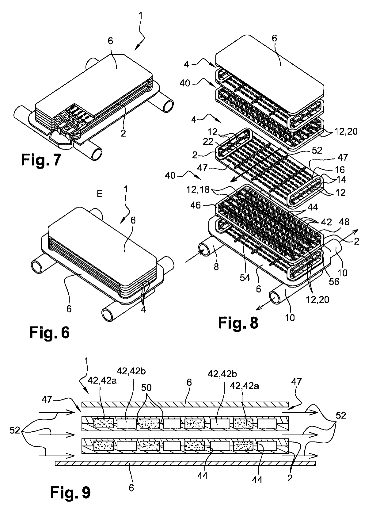
[0043]FIGS. 1 and 6 show a heat exchanger 1 according to embodiments of the invention.

[0044]The heat exchanger 1 is a plate-type heat exchanger. The heat exchanger 1 comprises a plurality of plates 2 stacked in a stacking direction E. The adjacent plates 2 are distant from each other, so as to define, between each pair of adjacent plates 2, an intermediate space 4 intended for a fluid circulation within the heat exchanger 1.

[0045]The plates 2 are configured to enable a heat exchange therethrough, that is to say from an intermediate space 4 to an adjacent intermediate space 4.

[0046]The intermediate spaces 4 may be closed, as illustrated in FIGS. 3 and 8, or open, as illustrated in FIG. 8. The closed intermediate spaces 4 have an outer wall 46 with a closed contour, which herein extends at the edge of the plates 2, between two adjacent plates 2, so as to delimit a closed volume. The open intermediate spaces 4 have at least two lateral openings 47, delimited for example by the edges op...


PUM

PropertyMeasurementUnit
sinuous trajectoryaaaaaaaaaa
thermally conductiveaaaaaaaaaa
thicknessaaaaaaaaaa

Abstract

This heat exchanger (1) comprises a stack of plates (2) spaced apart in such a way as to present an assembly of intermediate spaces (4) allowing a fluid circulation between the plates (2). Further, the assembly of intermediate spaces (4) comprises a plurality of intermediate multi-fluid spaces (40) each intended for circulation of a plurality of fluids between two adjacent plates (2), and each partitioned into a plurality of compartments (42) separated from each other in a sealed manner. Each compartment (42) is configured for the circulation of one fluid from the plurality of fluids, and is in fluid communication with one of the compartments (42) of a distinct intermediate multi-fluid space (40).

Description

CROSS REFERENCE TO RELATED APPLICATIONS[0001]This application is a National Stage of PCT Application No. PCT / FR2017 / 050945 filed on Apr. 21, 2017, which claims priority to French Patent Application No. 16 / 53647 filed on Apr. 25, 2016, the contents each of which are incorporated herein by reference thereto.TECHNICAL FIELD[0002]The present invention concerns a heat exchanger, and a vehicle comprising this heat exchanger.BACKGROUND[0003]The plate heat exchangers traditionally comprise several stacked aluminum plates so as to form an intermediate space between the adjacent plates intended for the circulation of a fluid. Conventionally, the heat exchangers comprise a first group of intermediate spaces fluidly connected to each other for the circulation of a first fluid through the stack of plates, and a second group of intermediate spaces fluidly connected to each other for the circulation of a second fluid through the stack of plates. The intermediate spaces of the first group conventio...

Claims


Application Information

Patent Timeline
Patent Type & Authority Applications(United States)
IPC IPC(8): F28F21/06F28D9/00F28F3/04
CPCF28F21/065F28D9/0043F28D9/005F28D9/0056F28F3/04B60H1/00321F28F21/067
Inventor ROSSIGNOL, VINCENTWAYMEL, GILLESDEMANGEOT, JEROME
Owner NOVARES FRANCE
Why Eureka
Try Eureka