Touch display device

a display device and touch technology, applied in the direction of instruments, computing, electric digital data processing, etc., can solve the problems of malfunction, failure to perform failure to meet the requirements of normal operation of the output switch of the data driver, so as to prevent display defects

Active Publication Date: 2019-04-25
LG DISPLAY CO LTD
View PDF1 Cites 20 Cited by
  • Summary
  • Abstract
  • Description
  • Claims
  • Application Information

AI Technical Summary

Benefits of technology

[0011]In various embodiments, the present disclosure provides a touch display device capable of preventing display defects,

Problems solved by technology

However, when USB power is off and then is supplied again under a sleep mode condition in which main power is off and only USB power is used in a set test procedure, a module setup procedure and the like, a malfunction may occur.
Furthermore, when the USB power is supplied first before the main power is provided according to a power sequence of a set, a malfunction may also occur.
For example, when the USB power is off and then is supplied again under a sleep mode condition in which the main power is off and only the USB power is supplied, the touch/data driver cannot perform an initialization process because a timing controller using the main power is turned off, and thus output switches of the data driver cannot perform norm

Method used


Image

  • Touch display device
  • Touch display device
  • Touch display device

Examples


Embodiment Construction

[0026]Hereinafter, embodiments of the present disclosure will be described with reference to the attached drawings.

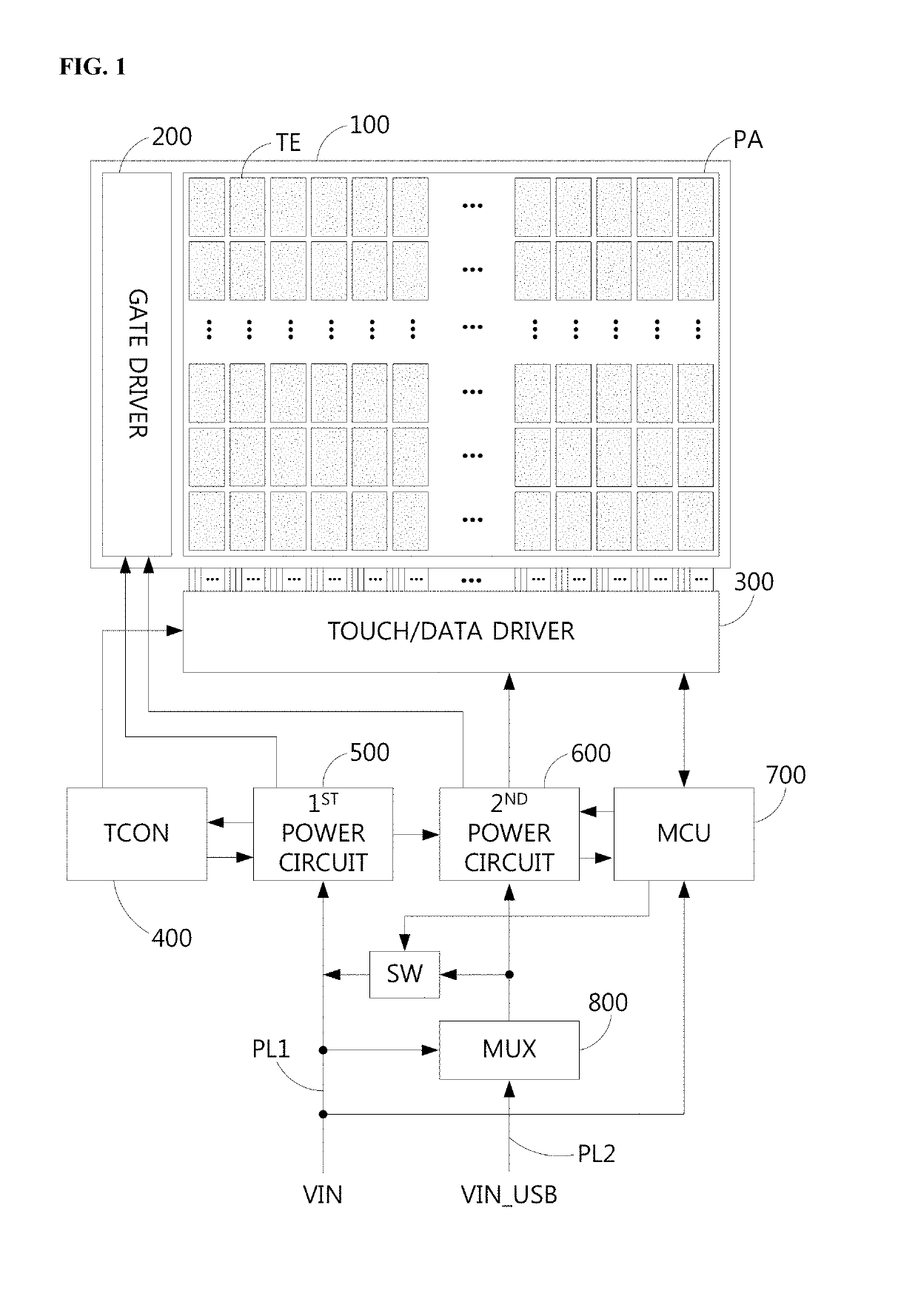
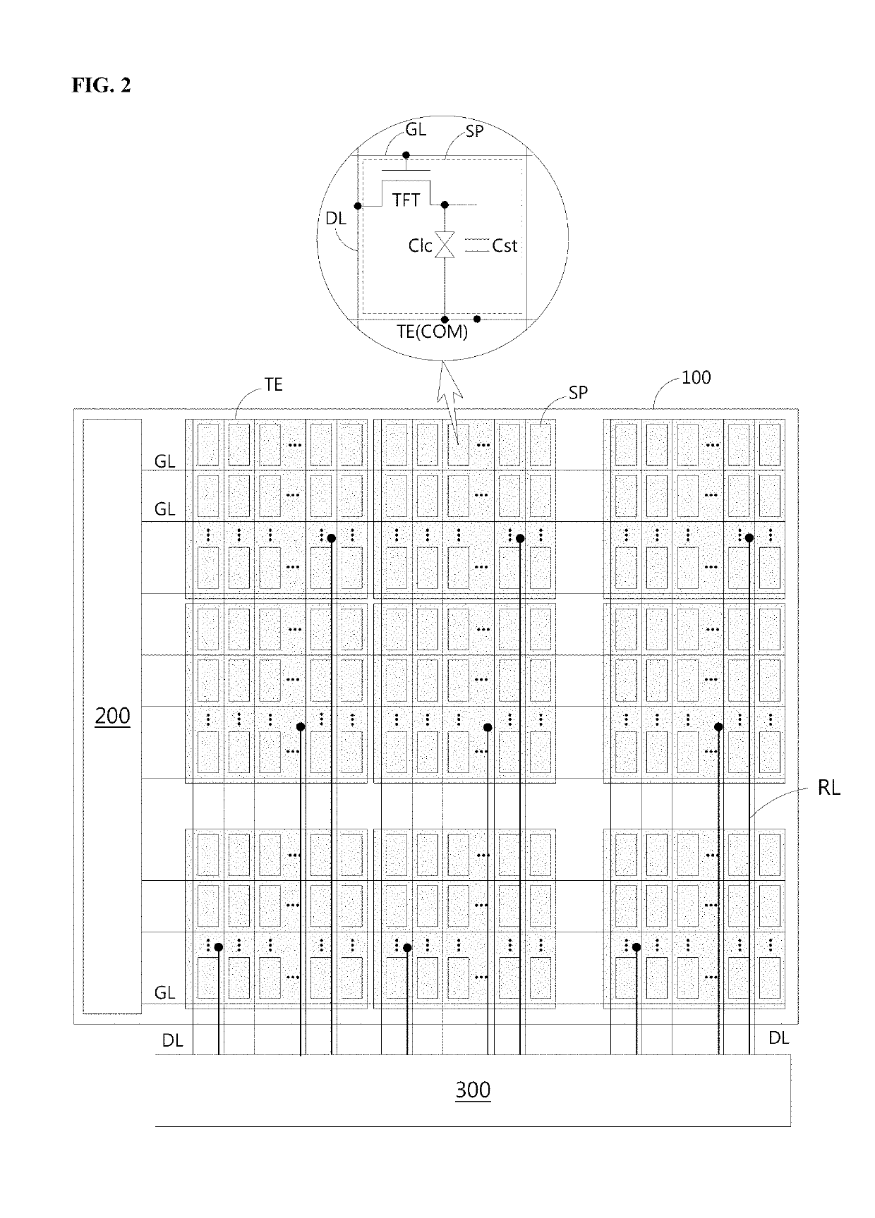
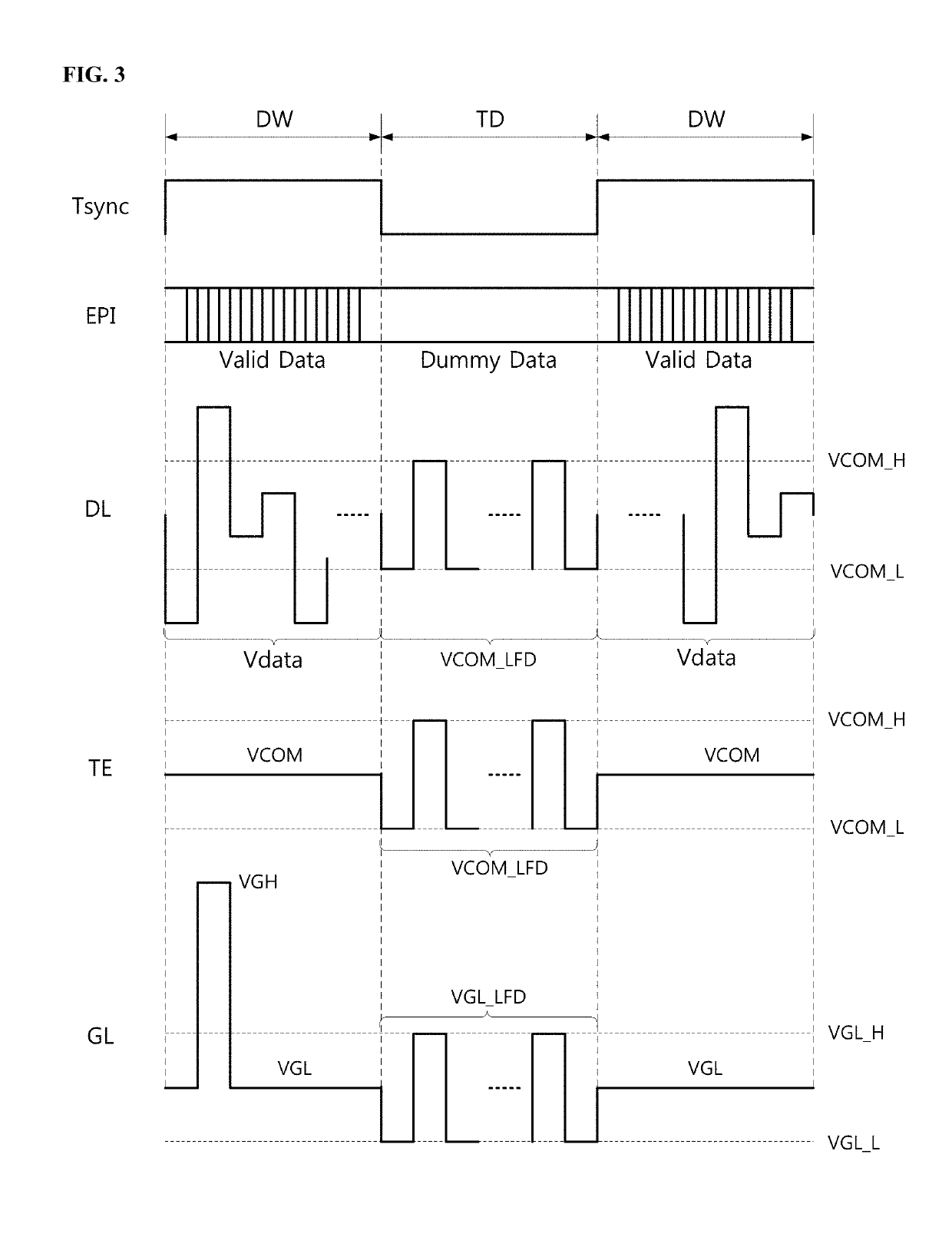
[0027]FIG. 1 is a block diagram schematically illustrating a configuration of a touch display device according to an embodiment of the present disclosure. FIG. 2 is a diagram illustrating configurations of touch electrodes and sub-pixels in the touch display panel according to an embodiment. FIG. 3 is a driving waveform diagram with respect to certain periods of the touch display device according to an embodiment. FIG. 4 is a block diagram illustrating the configuration of the touch display device according to an embodiment, which focuses on power circuits.

[0028]Referring to FIG. 1, the touch display device includes a panel 100, a gate driver 200, a touch / data driver 300, a timing controller (TCON) 400, a first power circuit 500, a second power circuit 600, and a microcontroller unit (MCU) 700.

[0029]The panel 100 has touch and display functions, displays an image throug...


PUM


Abstract

A touch display device can include a panel including touch electrodes; a touch/data driver to drive data lines and the touch electrodes of the panel, read out capacitance variations in the touch electrodes and output sensing data; a gate driver to drive gate lines of the panel; a timing controller to control display operations of the touch/data driver and the gate driver; a microcontroller unit (MCU) to control touch driving and sensing operations of the touch/data driver; a first power circuit to drive the timing controller and the gate driver using a main voltage supplied through a first power line; a multiplexer to output one of a universal serial bus (USB) voltage supplied through a second power line and the main voltage supplied through the first power line; a second power circuit configured to drive the touch/data driver, the gate driver and the MCU based on an output voltage from an output of the multiplexer; and a switch connected between the output of the multiplexer and the second power line, the switch being configured to switch the output of the multiplexer to the second power line.

Description

CROSS-REFERENCE TO RELATED APPLICATIONS[0001]This application claims the priority benefit of Korean Patent Application No. 10-2017-0138131, filed in the Republic of Korea on Oct. 24, 2017, which is hereby incorporated by reference as if fully set forth herein.BACKGROUNDTechnical Field[0002]The present disclosure relates to a touch display device capable of performing normal touch driving and sensing operations irrespective of a main power and auxiliary power supply sequence and preventing display defects.Description of the Related Art[0003]A touch sensor capable of inputting information through touch applied to a display screen is applied to various displays, such as notebook computers, monitors and home appliances as well as portable information devices such as smartphones.[0004]Touch techniques for displays include an add-on type, in which a touch panel is attached to a display panel, and an in-cell type, in which touch electrodes are embedded in a display panel. The in-cell type ...

Claims


Application Information

Patent Timeline
IPC IPC(8): G06F3/041G06F3/044G06F3/047G09G3/20
CPCG06F3/0412G06F3/0416G06F3/044G06F3/047G09G3/20G09G2310/08G09G2330/021G06F3/0418G06F3/0446G06F3/04166G06F1/3265G06F1/3206G06F3/04164
Inventor JANG, HOONCHO, SOON-DONGJANG, WON-YONG
Owner LG DISPLAY CO LTD
Why Eureka
Try Eureka