Charging control apparatus, charging control method and computer readable medium thereof
Active Publication Date: 2019-04-25
NAT CHUNG SHAN INST SCI & TECH
View PDF3 Cites 6 Cited by
Summary
Abstract
Description
Claims
Application Information
AI Technical Summary
This helps you quickly interpret patents by identifying the three key elements:
Problems solved by technology
Method used
Benefits of technology
Benefits of technology
The patent is about a charging control technique that can automatically choose the best charging mode for a battery based on its voltage, remaining capacity, and temperature. This helps to improve efficiency and prevent the battery from overheating.
Problems solved by technology
These charging approaches vary in the charging speed, the impact on the battery life, the complexity of the circuit implementation, and the cost.
The battery produces high current, so the sudden rise in temperature occurs in the battery.
Although the charging time will be greatly reduced, the battery will produce a higher temperature, resulting in a lower battery life.
This method can protect the battery and extends the battery life, but this method cannot determine whether the battery is fully charged.
From the above discussion, the constant voltage charging method is simple in circuit design, but the charging speed is slow.
The constant current charging method is simple in circuit implementation design and fast in charging, but the charge current is large and may damage the battery.
The pulse charging method can reduce the charging time and extend the battery life, but the disadvantage is the high cost and the implementation is relatively difficult.
Additionally, the constant current and constant voltage charging method is simple, but the charging speed is still slow.
Therefore, the conventional charging approaches vary in the charging speed, the impact on the battery life, the complexity of the circuit implementation, and the cost.
Method used
Image
Click on the blue label to locate the original text in one second.
Reading with bidirectional positioning of images and text.
Examples
example 1
[0061]In example 1, a test is conducted for determination of charging parameters, wherein a maximum output current of 60 A (i.e., 1 C) is set for the test. The charging parameters for a five-stage charging mode are: 54 A (0.9 C), 49.5 A (0.825 C), 39 A (0.65 C), 31.5 A (0.525 C), 25.5 A (0.425 C); and a trickle charging parameter is: 9 A (0.15 C), wherein the corresponding charging currents decrease successively or in a stepwise manner and a voltage of 460V is set. Referring to FIG. 7, a diagram of battery temperature with respect to time illustrates both tests respectively according to charging control as indicated in block S20 of FIG. 4 (curve C11), and a constant current charging method (curve C12).
example 2
[0062]In example 2, a test is conducted for determination of charging parameters, wherein a maximum output current of 100 A (i.e., 1 C) is set for the test. The charging parameters for a five-stage charging mode are: 90 A (0.9 C), 82.5 A (0.825 C), 65 A (0.65 C), 52.5 A (0.525 C), 42.5 A (0.425 C); and a trickle charging parameter is: 15 A (0.15 C), wherein a voltage of 460V is set. Referring to FIGS. 8A and 8B, FIG. 8A is a diagram of battery temperature with respect to time, illustrating both tests respectively according to charging control as indicated in block S20 of FIG. 4 (curve C21), and a constant current charging method (curve C22), and FIG. 8B is a diagram of battery voltage with respect to time, illustrating both an example according to charging control as indicated in block S20 of FIG. 4 (curve C31), and a constant current charging method (curve C32).
example 3
[0063]In example 3, a test is conducted for determination of charging parameters, wherein a maximum output current of 100 A (i.e., 1 C) is set for the test. The charging parameters for a five-stage charging mode are: 90 A (0.9 C), 82.5 A (0.825 C), 60 A (0.60 C), 52.5 A (0.525 C), 42.5 A (0.425 C); and a trickle charging parameter is: 15 A (0.15 C), wherein a voltage of 460V is set. Referring to FIGS. 9A and 9B, FIG. 9A is a diagram of battery temperature with respect to time, illustrating both tests respectively according to charging control as indicated in block S20 of FIG. 4 (curve C41), and a constant current charging method (curve C42), and FIG. 9B is a diagram of battery voltage with respect to time, illustrating both tests respectively according to charging control as indicated in block S20 of FIG. 4 (curve C51), and a constant current charging method (curve C51).
[0064]As can be observed from FIGS. 7 and 9A, during the charging of a battery set by the constant current chargin...
PUM
Abstract
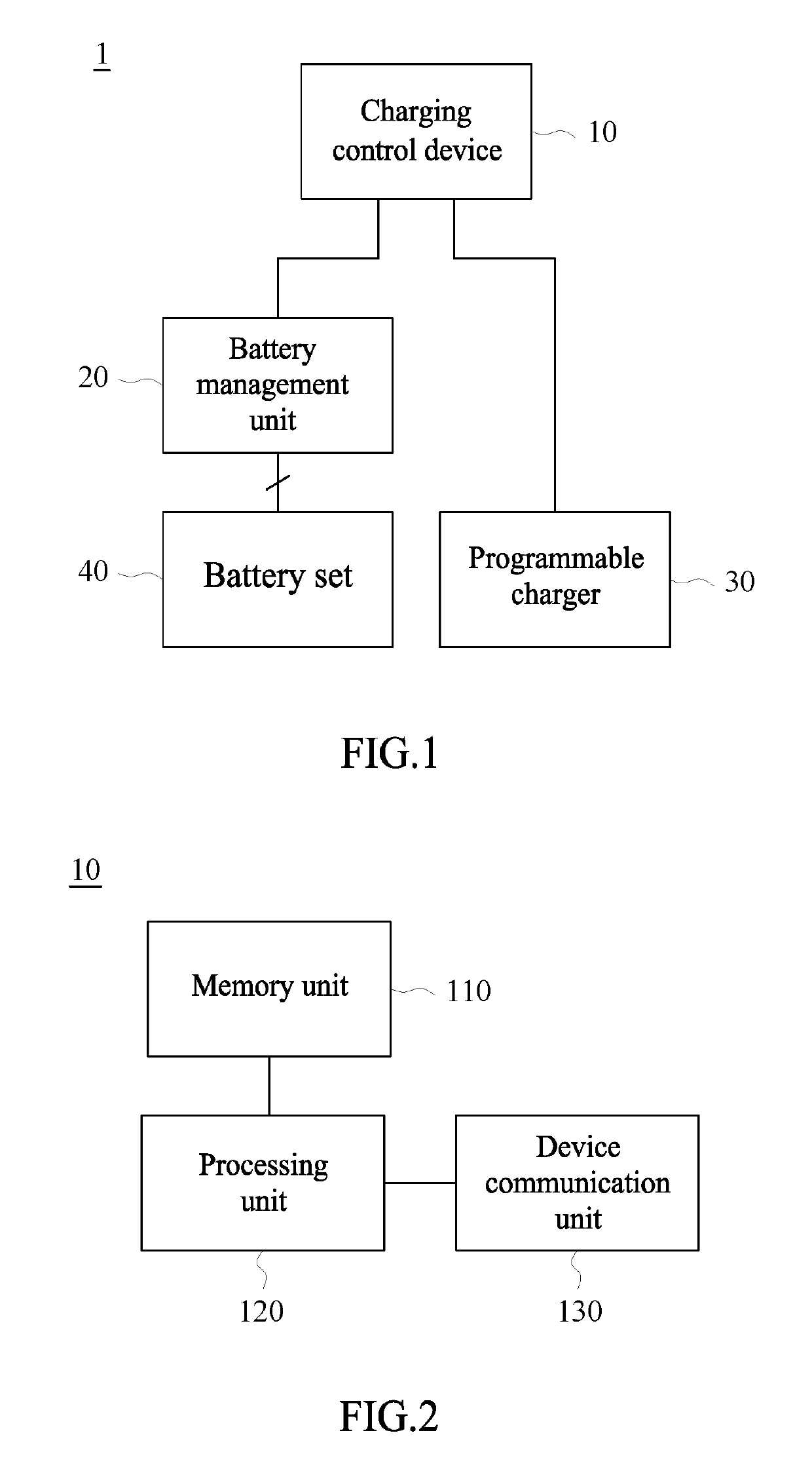
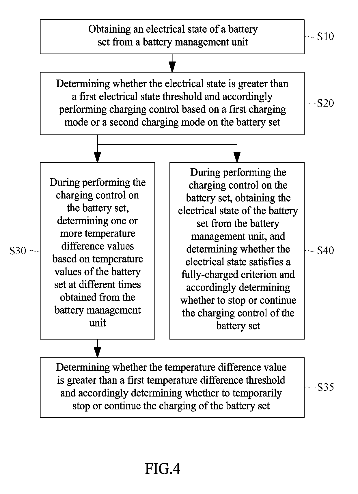
A charging control method includes the following. (a) An electrical state of a battery set is obtained. (b) Whether the electrical state is greater than a first electrical state threshold is determined and charging control based on a first charging mode or a second charging mode on the battery set is performed accordingly. (c) During the charging control on the battery set, at least one temperature difference value is determined based on temperature values of the battery set at different times. (d) Whether the temperature difference value is greater than a first temperature difference threshold is determined and whether to temporarily stop or continue the charging is determined accordingly. (e) During the charging control on the battery set, the electrical state is obtained, and whether the electrical state satisfies a fully-charged criterion is determined and whether to stop or continue the charging control is determined accordingly.
Description
FIELD OF THE INVENTION[0001]The present disclosure relates to charging control technology, and in particular to charging control apparatus, charging control method and computer readable medium thereof.BACKGROUND OF THE INVENTION[0002]There are a number of conventional approaches to battery charging such as constant voltage charging method, constant current charging method, trickle charging method, and pulse charging method. These charging approaches vary in the charging speed, the impact on the battery life, the complexity of the circuit implementation, and the cost. It is discussed briefly as below.[0003]The constant voltage charging method provides a constant voltage to charge the battery from the beginning to the end of charging. In the beginning of charging the battery, the charging voltage is greater than the battery voltage. The battery produces high current, so the sudden rise in temperature occurs in the battery. As the battery capacity increases, the battery voltage will be...
Claims
Application Information
Patent Timeline
Application Date:The date an application was filed.
Publication Date:The date a patent or application was officially published.
First Publication Date:The earliest publication date of a patent with the same application number.
Issue Date:Publication date of the patent grant document.
PCT Entry Date:The Entry date of PCT National Phase.
Estimated Expiry Date:The statutory expiry date of a patent right according to the Patent Law, and it is the longest term of protection that the patent right can achieve without the termination of the patent right due to other reasons(Term extension factor has been taken into account ).
Invalid Date:Actual expiry date is based on effective date or publication date of legal transaction data of invalid patent.

