[0039]It should be understood that the appended drawings are not necessarily to scale, presenting a somewhat simplified representation of various features illustrative of the basic principles of the disclosure. The specific design features of the present disclosure as disclosed herein, including, for example, specific dimensions, orientations, positions, and shapes will be determined in part by the particular intended application and use environment. In the figures, reference numbers refer to the same or equivalent parts of the present disclosure throughout the several figures of the drawing.
DETAILED DESCRIPTION OF THE EMBODIMENTS
[0040]Hereinafter reference will now be made in detail to various embodiments of the present disclosure, examples of which are illustrated in the accompanying drawings and described below. While the disclosure will be described in conjunction with certain embodiments, it will be understood that present description is not intended to limit the disclosure to those embodiments. On the contrary, the disclosure is intended to cover not only the disclosed embodiments, but also various alternatives, modifications, equivalents and other embodiments, which may be included within the spirit and scope of the disclosure as defined by the appended claims.
[0041]Throughout the description, it will be understood that when a component is referred to as being “comprising” any component, it does not exclude other components, but can further comprises the other components unless otherwise specified. As used herein, the singular forms “a,”“an,” and “the” are intended to include the plural forms as well, unless the context clearly indicates otherwise. As used herein, the term “and/or” includes any and all combinations of one or more of the associated listed items.
[0042]It is understood that the term “vehicle” or “vehicular” or other similar term as used herein is inclusive of motor vehicles in general such as passenger automobiles including sports utility vehicles (SUV), buses, trucks, various commercial vehicles, watercraft including a variety of boats and ships, aircraft, and the like, and includes hybrid vehicles, electric vehicles, plug-in hybrid electric vehicles, hydrogen-powered vehicles and other alternative fuel vehicles (e.g., fuels derived from resources other than petroleum). As referred to herein, a hybrid vehicle is a vehicle that has two or more sources of power, for example both gasoline-powered and electric-powered vehicles.
[0043]Hereinafter, embodiments of the present disclosure will be described in detail with reference to the accompanying drawings.
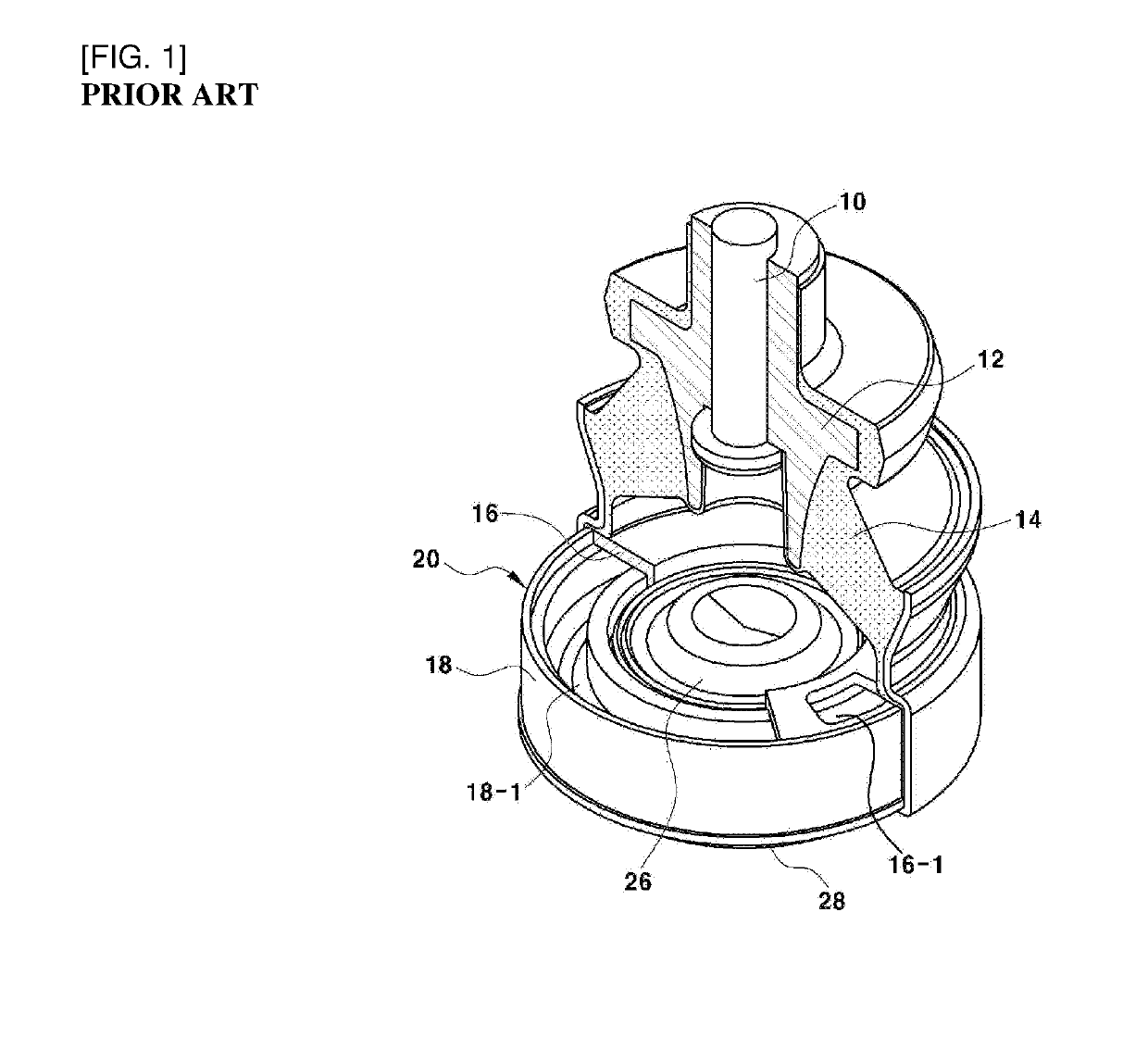
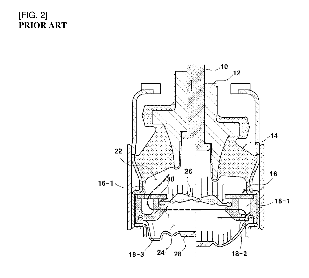
[0044]As shown in FIG. 7, a hydraulic mount according to embodiments of the present disclosure is configured to include a core bush 12 coupled with a bolt 10; a main rubber 14 formed on an outer diameter surface of the core bush 12 by the method of a curing adhesion and the like; an orifice portion 20 coupled to a lower portion of the main rubber 14 to divide an upper fluid chamber 22 and a lower fluid chamber 24; and a lower rubber film 28 connected to a vehicle body using the bolt and the like as a medium. The bolt 10 is coupled with the core bush 12; and an outer diameter portion of the core bush 12 is formed with the main rubber 14 by a method of curing adhesion or the like.
[0045]Further, a lower portion of the main rubber 14 is positioned with an orifice portion 20 that the upper plate 16 and the lower plate 18 are coupled to each other; and a lower portion of the orifice portion 20 is mounted with the lower rubber film 28 connected to the vehicle body using the bolt and the like as a medium.
[0046]In this case, the lower plate 18 is formed with a fluid path 18-1 which is a first orifice having a concave groove structure on an upper surface portion thereof and simultaneously, is produced as a ring shape that a lower inlet and outlet port 18-2 is formed on a predetermined position of the fluid path 18-1; and the upper plate 16 is produced by a ring-shaped plate body having an upper inlet and outlet port 16-1 to cover the fluid path 18-1 of the lower plate 18 and to be coupled thereto.
[0047]Particularly, a central portion of the orifice portion 20 is mounted with a membrane 26 of a rubber material which substantially divides the upper fluid chamber 22 and the lower fluid chamber 24. That is, the membrane 26 is interposed between the upper plate 16 and the lower plate 18 to substantially divide the upper fluid chamber 22 and the lower fluid chamber 24.
[0048]In this case, a gap between an outer diameter portion of the membrane 26 and the inner diameter portions of the upper plate 16 and the lower plate 18, as illustrated in FIG. 10, is formed by a nozzle portion 30 which is a second orifice allowing the fluid movement between the upper fluid chamber 22 and the lower fluid chamber 24.
[0049]Particularly, according to the present disclosure, as illustrated in FIGS. 5 to 7, the upper plate 16 of the orifice portion 20 has a concave groove portion 16-2 and a fixing end 16-3 repeatedly and uniformly formed along the circumference on the inner diameter surface thereof.
[0050]In this case, the concave groove portion 16-2 for increasing an upper exposed area of the membrane 26 is concavely formed toward the outer diameter direction of the upper plate 16; and the fixing end 16-3 for fixing the membrane 26 performs the locking function available for contacting an edge upper surface of the membrane 26.
[0051]Accordingly, the upper exposed area of the membrane 26, that is, the area exposed toward the upper fluid chamber 22, as illustrated in the comparison diagram of the accompanying FIG. 11, becomes the status increased compared to the membrane included in the conventional fluid mount.
[0052]Preferably, eight concave groove portions 16-2, in total, are formed at a 45° interval along the circumference on the inner diameter surface of the upper plate 16. As a result, the upper exposed area of the membrane is increased and simultaneously, the locking area for the fixing end 16-3 is used to fix the membrane 26.
[0053]Meanwhile, as illustrated in FIG. 8, an upper surface of the outer circumference of the membrane 26 is formed with a stepwise-type step portion 26-1 for the line-contact with a lower surface of the fixing end 16-3 of the upper plate 16; and also the stepwise-type step portion 26-1 for the line-contact with the lower plate 18 is formed on a lower surface of the outer circumference of the membrane 26.
[0054]Accordingly the outer circumference of the membrane 26 has a thickness which gradually reduces toward the outer diameter direction by the stepwise-type step portion 26-1 formed on the upper and lower surfaces thereof.
[0055]Further, as illustrated in FIGS. 9 and 10, as the outer circumference of the membrane 26 has the gradually reducing thickness to be thereby formed as the stepwise-type step portion 26-1, the lower surface of the fixing end 16-3 of the upper plate 16 for the line-contact with the stepwise-type step portion 26-1 is formed as the inclined surface 16-4 and simultaneously, the inner circumference of the lower plate 18 is also formed as an incline.
[0056]Meanwhile, since the inner circumference of the lower plate 18 is integrally formed with a membrane stopper 34 that a fluid through-hole 32 is formed, the membrane stopper 34, in the case that the membrane 26 is moved in the downward by the fluid pressure, functions as preventing the membrane 26 from being escaped.
[0057]Herein, an operating flow on the hydraulic mount according to embodiments of the present disclosure having the configuration will be described as follows.
[0058]As shown in FIG. 12, when a small displacement vibration (e.g., due to an idle vibration or driving a vehicle on a smooth road) is input to the hydraulic mount, the fluid within the upper fluid chamber 22 operates on the membrane 26 and simultaneously, the membrane 26 performs the deformation moving in the downward to thereby absorb the small displacement vibration.
[0059]Of course, in the case that the vibration slightly larger than the small displacement vibration (is input to the hydraulic mount, the fluid within the upper fluid chamber 22 may absorb the vibration while moving to the lower fluid chamber 24 through the nozzle portion 30 between the output diameter portion of the membrane 26 and the inner diameter portions of the upper plate 16 and the lower plate 18, thereby obtaining a larger improved effect of Noise, Vibration & Harshness (NVH).
[0060]As shown in FIG. 13, in the case that a large displacement vibration (e.g., driving a vehicle on a rough road) is input to the hydraulic mount, the fluid within the upper fluid chamber 22 enters into and circulates in the fluid path 18-1 of the lower plate 18 through the upper inlet and outlet port 16-1 of the upper plate 16, and then the high reduction absorbing the large displacement vibration is implemented while passing through the lower inlet and outlet port 18-2 and being filled into the lower fluid chamber 24 through the lower inlet and outlet port 18-2 of the lower plate 18.
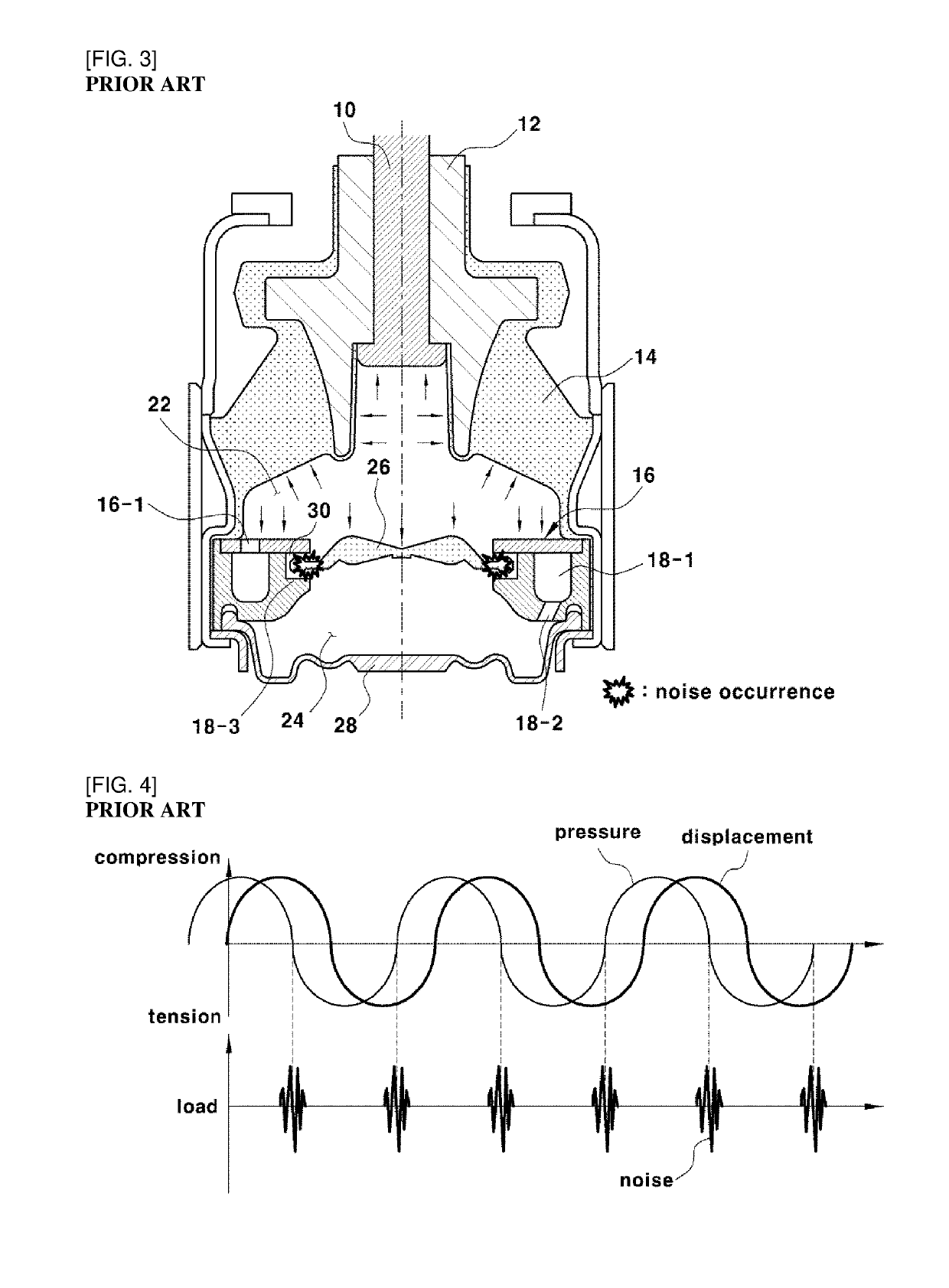
[0061]In this case, when the large displacement vibration is input to the hydraulic mount, the fluid within the upper fluid chamber 22 may excite the membrane 26 by a large pressure, thereby, conventionally, occurring the rattle noise due to the hitting while the outer circumference of the membrane 26 has the surface-contact (referring to FIG. 3) with the surface of the nozzle portion 30.
[0062]However, when the fluid within the upper fluid chamber 22 excites the membrane 26 by a large pressure, the angular edge portion of the stepwise-type step portion 26-1 formed on the upper and lower surfaces of the outer circumference of the membrane 26 has the line-contact with an inclined surface 16-4 of the upper plate 16 or an inclined surface of the lower plate 18; and in this case, the contact collision may be distributed and absorbed by the line-contact, thereby minimizing the rattle noise.
[0063]The disclosure has been described in detail with reference to certain embodiments thereof. However, it will be appreciated by those skilled in the art that changes may be made in these embodiments without departing from the principles and spirit of the disclosure, the scope of which is defined in the appended claims and their equivalents.