
Heatsink and heatpipes

Inactive Publication Date: 2019-05-02
THIN TANKS
View PDF2 Cites 0 Cited by
  • Summary
  • Abstract
  • Description
  • Claims
  • Application Information

AI Technical Summary

Benefits of technology

The patent text describes a method of using heat pipes in a rotational mold to improve the process of removing a solidified product and reheating it for a new load of polyethylene powder. The heat pipes help to increase the rate at which heat is removed from the mold, and a small gap between the ends of the heat pipes helps to improve the structural integrity and shorten production cycles. Additionally, the heat pipes can be used without any sealed evaporating-condensing fluid, and the result is a water-tight tank.

Problems solved by technology

Molding thin tanks is a more difficult task, as it requires the structural inclusion of connections between the two vertical faces of the tank.
However, there remains an issue with such a system of molding, primarily due to the large surface area of the mold and the different shapes of product, which involve different rates of heat transfer resulting in uneven wall thickness and acute angles between surfaces can at times, depending upon the shape of the product that is being molded, result in excessive cycling times of the rotomold apparatus as well as differences in surface finish and structure.
We have observed that the stage of cooling and de-molding which are problematic when rotational molding thin tanks as due to their size the require additional cooling time to ensure that the thin walls of the structure have adequately cooled to reduce or eliminate the likelihood that the product will be de-molded whilst the polyethylene material has not adequately cooled to the appropriate temperature.
Failure to do so results in the thin plastic walls of the structure lacking the structural integrity to retain its desired shape and they begin to collapse or sag leading to deformation of the structure.

Method used


Image

  • Heatsink and heatpipes
  • Heatsink and heatpipes
  • Heatsink and heatpipes

Examples


Embodiment Construction

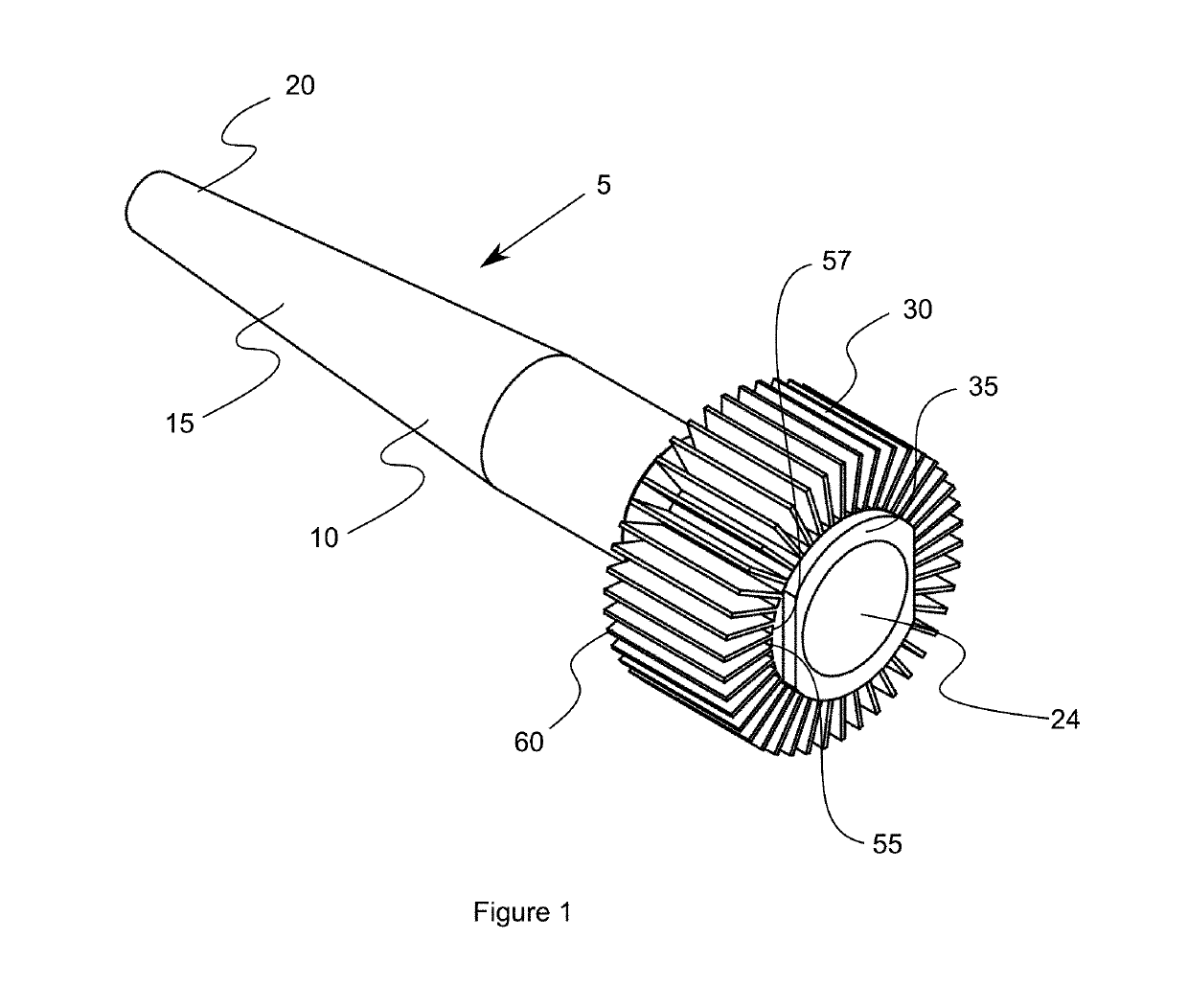
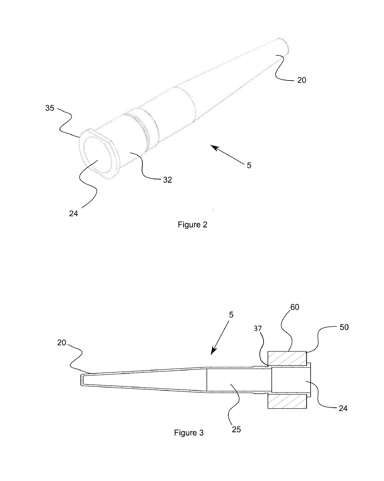
[0048]FIG. 1 shows a preferred embodiment of the present invention 5, having a main cylindrical body 10 with a conical section 15 tapering towards a first end 20. The heat-first end 20 is the end of the heat pipe 5 that is inserted into a cavity on a surface of a rotational mold. Opposite to the first end 20 is the second end 30, about which there is a thermal energy absorbing / dissipating means 50. The second end 30 has a substantially uniform outer diameter with an outer surface 32, and an end flange 35

[0049]The thermal energy absorbing / dissipating means 50 includes a circular main body 55 with an opening 57 shaped to allow the body 10 of the heat pipe 5 to be inserted into it and nestingly fit within. The heat pipe 5 can be press-fitted into the thermal energy absorbing / dissipating means so that there is a good surface-surface interaction between the thermal energy absorbing / dissipating means 50 and the condenser end 30, the flange 35 on the outer end of the second end 30 acting a...


PUM

PropertyMeasurementUnit
Energyaaaaaaaaaa
Heataaaaaaaaaa

Abstract

The invention provides a heat-pipe for a rotational molding apparatus.

Description

FIELD OF THE INVENTION[0001]This application claims Paris priority to Australian provisional application 2017904455 naming applicant THIN TANKS PTY LTD, local attorney reference 67458 DIA:JP, filed 2 Nov. 2017. This application incorporates by reference the foregoing Australian provisional application 2017904455.[0002]This invention relates primarily to the manufacture and configuration of water tanks, in particular to the production of rectangular thin tanks for domestic water storage using heat pipes within the mold to provide even and controlled heating and cooling of the mold.DESCRIPTION OF THE PRIOR ART[0003]Rotational molding is cycling process where polyethylene or other appropriate materials are placed inside a rotational mold as a powder. The mold is then heated to the desired temperature, the powder melts and, due to the rotational movement of the mold, the melted polyethylene forms an even coat over the internal surface of the mold. The process is made up of essential fou...

Claims


Application Information

Patent Timeline
IPC IPC(8): F28D15/04
CPCF28D15/04F28D2021/0029F28D2021/0077B29C33/04B29C41/46F28D15/0233F28D15/0275F28F1/14B29C41/42
Inventor SNELLING, PETER
Owner THIN TANKS
Learn More