Transformer winding fault diagnosis method based on wireless identification sensing

a technology of wireless identification and transformer winding, applied in the direction of electrical testing, measurement devices, instruments, etc., can solve the problems of reducing the reliability of power supply, increasing wiring costs and post-maintenance costs, and low economic benefits, so as to increase the running efficiency of a transformer and improve the efficiency. the effect of efficiency and easy implementation

Active Publication Date: 2019-05-02
WUHAN UNIV
View PDF0 Cites 12 Cited by
  • Summary
  • Abstract
  • Description
  • Claims
  • Application Information

AI Technical Summary

Benefits of technology

[0023]1. A transformer winding signal is wirelessly collected and transmitted by using a vibration sensor integrating a radio frequency identification function, implementing remote, wireless, and unmanned fault diagnosis on a transformer winding. The present invention is easy in implementation and increases the running efficiency of a transformer.
[0024]2. The vibration sensor integrating the radio frequency identification function includes a magnetic field energy obtaining apparatus disposed on an outer periphery of the transformer, energy of a magnetic field surrounding the transformer is captured, and is used as an energy source of the vibration sensor integrating the radio frequency identification function; the shape of the magnetic field energy obtaining apparatus is customized for high efficiency; in addition, vibration signal data is collected

Problems solved by technology

However, all of the foregoing four methods are offline diagnosis methods, require a transformer to exit a running state to perform fault diagnosis, and cannot implement fault diagno

Method used


Image

  • Transformer winding fault diagnosis method based on wireless identification sensing
  • Transformer winding fault diagnosis method based on wireless identification sensing
  • Transformer winding fault diagnosis method based on wireless identification sensing

Examples


Embodiment Construction

[0036]Reference will now be made in detail to the present preferred embodiments of the invention, examples of which are illustrated in the accompanying drawings. Wherever possible, the same reference numbers are used in the drawings and the description to refer to the same or like parts.

[0037]The following describes technical solutions of the present invention with reference to the accompanying drawings and relatively preferable embodiments in detail. The following relatively preferable embodiments are only used for describing and explaining the present invention, but do not constitute a limitation on the technical solutions of the present invention.

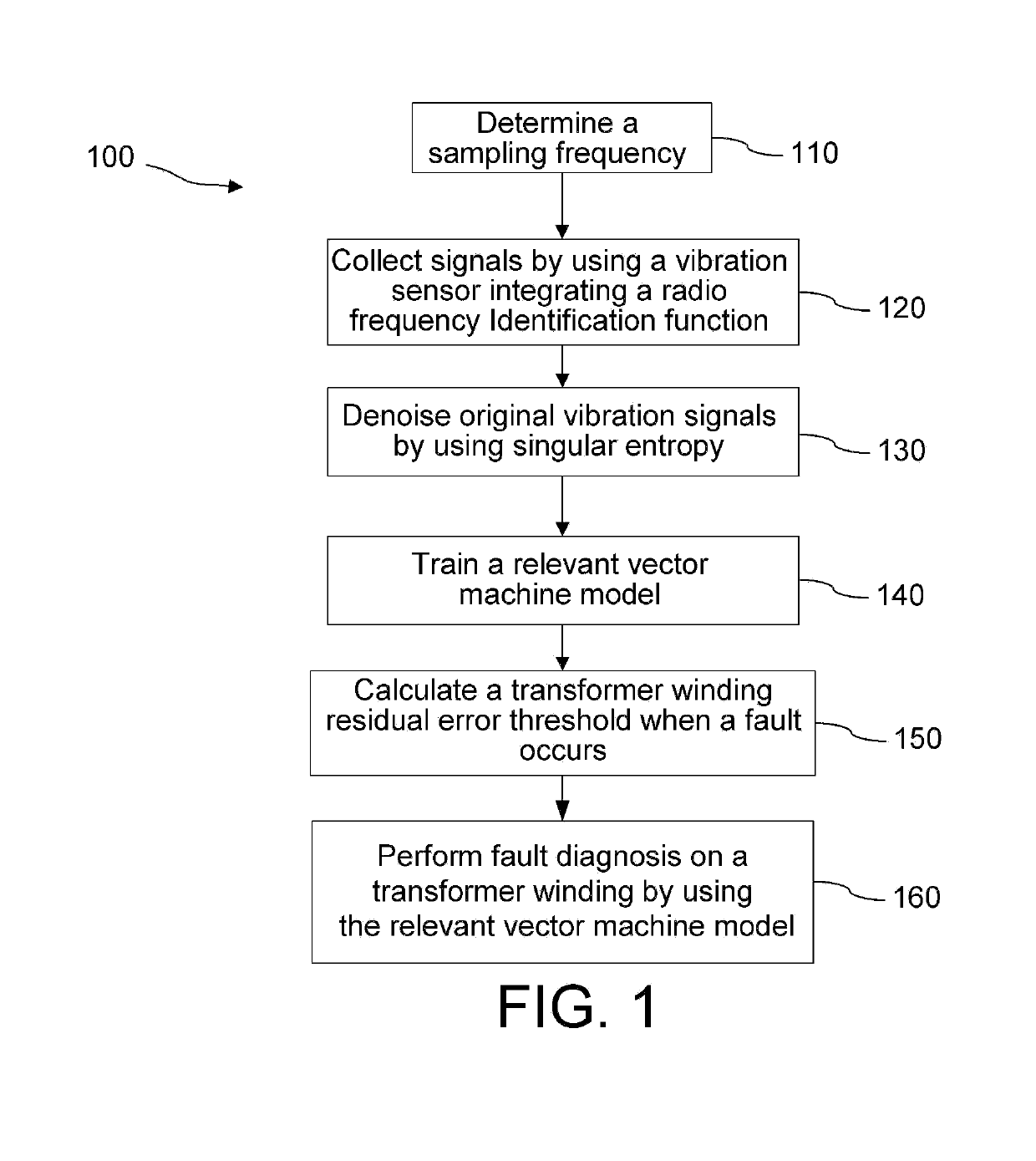
[0038]Referring to FIG. 1, FIG. 1 is a flowchart 100 of a transformer winding fault diagnosis method based on wireless identification sensing according to the present invention. The method includes the following steps:

[0039](1) In step 110, determine a sampling frequency, and step 120, respectively collect, by using a vibration sensor in...


PUM


Abstract

A transformer winding fault diagnosis method based on wireless identification sensing includes the following steps: collecting transformer winding vibration signals in a normal state and when a fault occurs; denoising the transformer winding vibration signals by using singular entropy, and randomly dividing the denoised transformer winding vibration signals in the normal state into two groups, where one group is training data, and the other group is original measurement data; using the denoised transformer winding vibration signals obtained when the fault occurs as original threshold data; reconstructing the original threshold data to obtain reconstructed threshold data, and obtaining a transformer winding residual error threshold when the fault occurs; and reconstructing the original measurement data to obtain reconstructed measurement data, obtaining corresponding residual error data, and comparing the residual error data with the residual error threshold, to implement fault diagnosis on the transformer winding. The present invention implements remote, wireless, and unmanned fault diagnosis on a transformer winding. The diagnosis efficiency is high, the workload of a maintenance person is reduced, and the running efficiency of a transformer is increased.

Description

CROSS-REFERENCE TO RELATED APPLICATION[0001]This application claims the priority benefit of China application serial no. 201711027358.3, filed on Oct. 27, 2017. The entirety of the above-mentioned patent application is hereby incorporated by reference herein and made a part of this specification.BACKGROUND OF THE INVENTION1. Field of the Invention[0002]The present invention relates to the field of transformer winding fault diagnosis, and in particular, to a transformer winding fault diagnosis method based on wireless identification sensing.2. Description of Related Art[0003]In a transformer substation, a running status of a transformer directly relates to the safety and reliability of power generation and power supply systems. Existing methods for performing fault diagnosis on a transformer mainly include methods such as an oil chromatography method, a low-voltage pulse method, a short-circuit impedance method, and a frequency response analysis method. However, all of the foregoing ...

Claims


Application Information

Patent Timeline
IPC IPC(8): G01R31/02G01P15/18
CPCG01R31/027G01P15/18G01R31/62G06F2218/04G06F2218/12G06F18/2433
Inventor HE, YIGANGWANG, TAOLI, BINGZHANG, HUILIU, KAIPEIHE, LIULU
Owner WUHAN UNIV
Why Eureka
Try Eureka