System and method for controlling a power generating unit

a power generating unit and system control technology, applied in adaptive control, process and machine control, instruments, etc., can solve problems such as delay voltage recovery, slow response of voltage controllers, and power systems with smaller scr values may experience undamaged voltage oscillations

Active Publication Date: 2019-05-02
GENERAL ELECTRIC CO
View PDF1 Cites 12 Cited by
  • Summary
  • Abstract
  • Description
  • Claims
  • Application Information

AI Technical Summary

Benefits of technology

[0004]In accordance with one embodiment of the present invention, a method is disclosed. The method includes receiving at least two measurement data sets from a location of integration of a power generating unit to an electrical grid. Each measurement data set includes a plurality of electrical parameters. The method further includes generating a grid model of the electrical grid based on the at least two measurement data sets. The grid model is characterized by an equivalent grid voltage and an equivalent grid impedance. The method further includes computing a strength value of the electrical grid based on the grid model, using the at least two measurement data sets. The method also includes controlling a power output of the power generating unit based on the strength value.

Problems solved by technology

Power systems having smaller SCR values may experience un-damped voltage oscillations due to fast response of voltage controllers associated with the power generation units, especially renewable energy sources.
The slow response of the voltage controllers would delay voltage recovery during start up conditions and other contingency situations.
Hence, use of the system strength value determined at the time of commissioning of operation of the power generating unit is not effective.
However, access to grid data for assessing strength value is not provided by the grid operators and regulatory authorities.

Method used


Image

  • System and method for controlling a power generating unit
  • System and method for controlling a power generating unit
  • System and method for controlling a power generating unit

Examples


Embodiment Construction

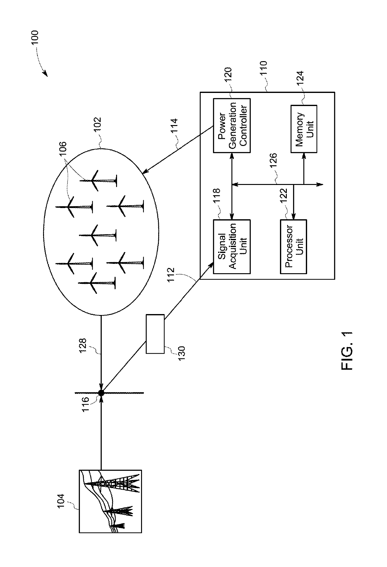
[0013]As will be described in detail herein, a system and a method for effectively controlling a power generating unit integrated with an electrical grid are disclosed. More particularly, a system and a method for controlling a power output of the power generating unit to enhance power transfer and stability of the power generating unit are disclosed. At least two measurement data sets are received from a location of integration of the power generating unit to the electrical grid. A grid model of the electrical grid is generated based on the at least two measurement data sets. A strength value of the electrical grid is computed based on the grid model using the at least two measurement data sets. A power output of the power generating unit is controlled based on the strength value.

[0014]The term “power generating unit” refers to any electrical power source with a wind farm being shown and described herein as example. The term “electrical grid” refers to a network interconnecting a p...


PUM


Abstract

A method for controlling a power output of a power generating unit includes receiving at least two measurement data sets from a location of integration of a power generating unit to an electrical grid. Each measurement data set includes a plurality of electrical parameters. The method further includes generating a grid model of the electrical grid based on the at least two measurement data sets. The grid model is characterized by an equivalent grid voltage and an equivalent grid impedance. The method further includes computing a strength value of the electrical grid based on the grid model, using the at least two measurement data sets. The method also includes controlling the power output of a power generating unit based on the strength value of the electrical grid.

Description

BACKGROUND[0001]Embodiments of the present invention relate generally to power generating units, and more particularly to a system and a method for effectively controlling a power generating unit integrated with an electric gird.[0002]In general, an electrical grid includes a plurality of power generating units and transmission lines interconnecting power generating stations with consumers. Stability of a power system is related to the ability of the electrical grid to maintain a system voltage. Power systems having a greater strength value experience smaller voltage change at a location of integration of the power generating unit with the electrical grid during an injection of reactive power compared to power systems having a lower strength value. The strength value of the power system is quantified by a short circuit ratio (SCR) defined as a ratio of a short circuit MVA (before connecting a generator to the grid) to the MW value of the generator. Power systems having smaller SCR v...

Claims


Application Information

Patent Timeline
Patent Type & Authority Applications(United States)
IPC IPC(8): H02J3/38G05B13/04F03D7/04
CPCH02J3/386G05B13/042F03D7/048H02J2003/007F03D7/0284H02J2203/20H02J2300/28H02J3/381Y02E10/72Y02E10/76Y02E60/00Y04S40/20H02J3/242Y04S10/22Y02E40/70
Inventor GADIRAJU, KASI VISWANADHA RAJUARAVIND, DEEPAKSAGI, DEEPAK RAJ
Owner GENERAL ELECTRIC CO
Why Eureka
Try Eureka