
Arrangement introduced in a device having a hook for anchoring a ladder to cables

a technology of cable anchoring and cable, which is applied in the direction of cables, hooks, and vehicles/pulleys, etc., can solve the problems of user falling, compromising the functionality of the cable support, and putting the users of the cable support in a state of risk, so as to achieve the effect of increasing efficiency without incurring any burden

Inactive Publication Date: 2019-05-09
LEVY JACQUES
View PDF19 Cites 6 Cited by
  • Summary
  • Abstract
  • Description
  • Claims
  • Application Information

AI Technical Summary

Benefits of technology

The invention is a hook-type device for ladder anchorage in cables that improves safety and efficiency. The device has been designed to optimize its mechanical and functional qualities, as well as the shape, layout, and location of its parts and components. This results in an improved performance without adding any burden. The invention is easy to implement and provides complete safety for its users.

Problems solved by technology

In spite of the great utility of this safety device, there are some conditions that can compromise its functionality, putting the users of the service ladders supported on cables in condition of risk.
One such condition is the possibility of the hook-type safety device to move sideways and destabilize the ladder, causing the user to fall.
There is no locking apparatus on the market that prevents the transverse movement of the hook-type safety device on the steps of the ladder, and such sideways movement may cause the safety equipment to be uncoupled from the ladder.
Another risky situation is the possibility of the rope fastening the hook to untie from its tying point, causing the hook to be released from the support cable.
There is at present no safety system preventing improper opening of the hook.

Method used


Image

  • Arrangement introduced in a device having a hook for anchoring a ladder to cables
  • Arrangement introduced in a device having a hook for anchoring a ladder to cables
  • Arrangement introduced in a device having a hook for anchoring a ladder to cables

Examples


Embodiment Construction

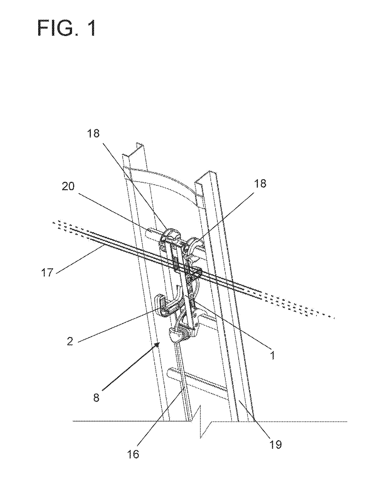
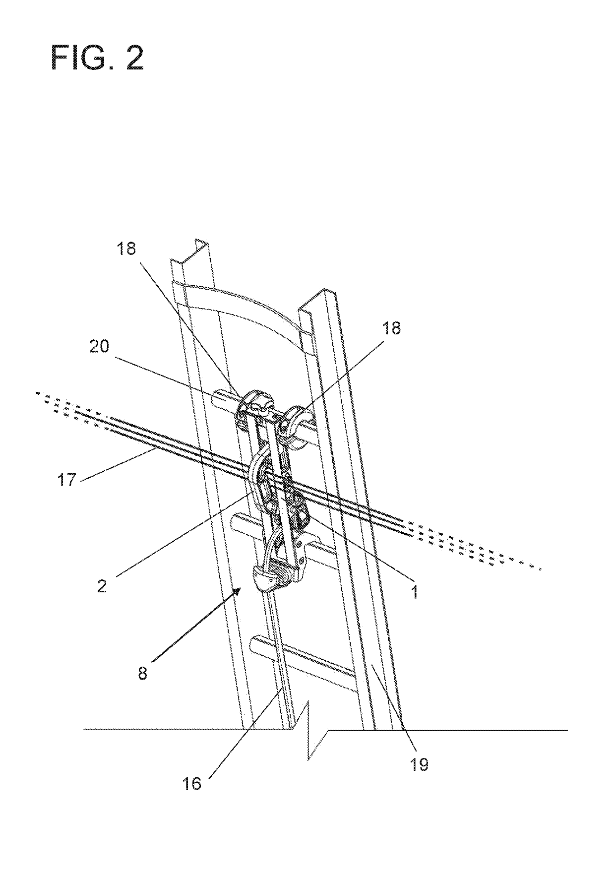
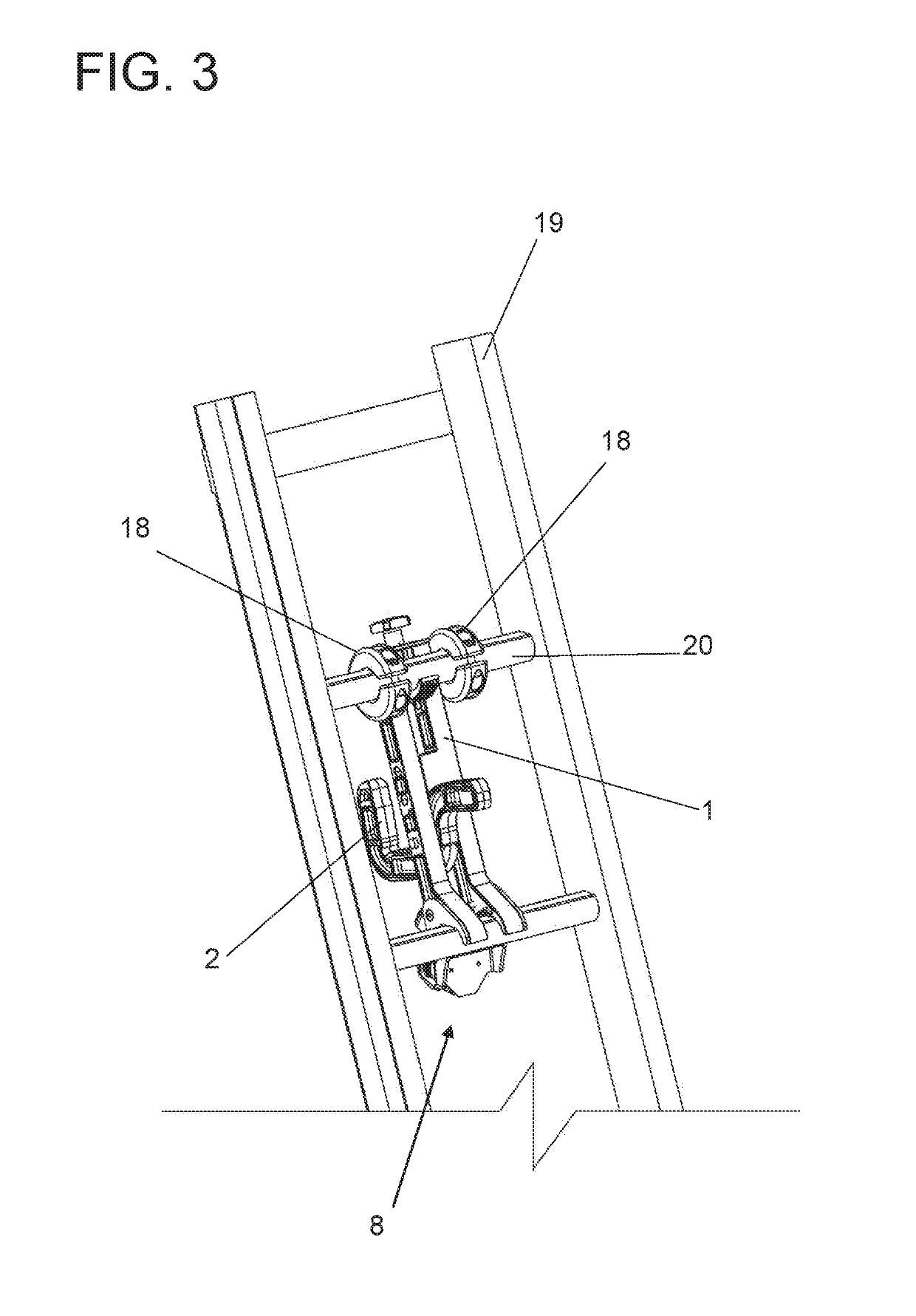
[0031]In accordance with the above figures, the object of this invention, essentially consists of a main vertical frame (1) of prismatic rectangular geometry provided with a hinged hook (2) at its center, the rear end of which has an extension in which a through hole (3) is provided for attaching the rope (16).

[0032]The upper end of the main frame (1) has a longitudinal threaded shaft (4), provided with a handle (5) in the upper portion with a rectangular prismatic one-piece (6) coupled to said threaded shaft (4), which is attached to a rectangular opening in the upper portion of the main frame (1), with the one-piece (6) having on its rear face a concave surface (7) that tangentially embraces the bottom of the step.

[0033]At the lower end of the main frame (1), there is a rope grip (8) consisting laterally of an U-shaped support (9) which bears two semi-cylindrical elements (10) with grooved-like teeth positioned side by side, in which upper portions there is a rope limiting element...


PUM


Abstract

The present patent application belongs to the field of workplace safety equipment and proposes an improvement to a device provided with a hook for anchoring a ladder to cables. The ladder is formed by a main structure (1) having in the center thereof an articulated hook (2). The main structure (1) comprises an extensible shaft in the upper portion thereof, allowing it to be coupled between two steps of a service ladder. In order to overcome drawbacks, a rope holder (8) has been developed, which is arranged in the lower portion of the main structure and locks the rope tying the hook (2), preventing the hook (2) from turning upside down or from opening. The rope holder also has two lateral toroidal locks (18) coupled to the step (20) of the ladder, each on one side of the main structure (1), preventing the main structure from shifting

Description

FIELD OF THE INVENTION[0001]The purpose of this utility model patent is an improvement in rope ladder anchoring equipment, which is in the field of occupational safety equipment. Such ladder anchoring equipment comprises a mechanism to be coupled between two steps of the service ladder and is provided with a hinged hook, the function of which is to tenaciously attach a ladder to a horizontal cable, be it electric power, telephony, steel cable, or the like, with the purpose of avoiding the movement of the ladder, which would cause the worker to fall, as well as to safeguard the worker from a fatal fall due to sudden illness, and to which original constructive layout was given, aiming to improve its performance compared to other models commonly offered on the market.[0002]The purpose of this patent application is an improvement aiming to prevent unintentional sideways movement of the device incorporating the hinged hook and also to prevent the hook itself from inadvertently moving dur...

Claims


Application Information

Patent Timeline
IPC IPC(8): E06C7/18E06C7/48
CPCE06C7/188E06C7/48F16B45/02A62B1/16F16G11/143E06C7/186E06C7/14E06C1/36
Inventor LEVY, JACQUES
Owner LEVY JACQUES
Learn More