Fiber-optic based traffic and infrastructure monitoring system

a traffic and infrastructure monitoring and fiber optic technology, applied in the direction of instruments, roads, constructions, etc., can solve the problems of high installation cost, large number of electronic measurement elements in the current road monitoring system, and relatively high cost of known sensor devices

Active Publication Date: 2019-05-09
OPTICS11 BV +1
View PDF0 Cites 13 Cited by
  • Summary
  • Abstract
  • Description
  • Claims
  • Application Information

AI Technical Summary

Benefits of technology

[0006]It is an object of the present invention to provide an improved arrangement of a traffic infrastructure and an optic sensor system.
[0008]Surprisingly, by using a sensor system according to the present invention, it is provided a high-accuracy measurement system that has almost no influence on the road behavior so this behavior can be modelled in a more accurate way.
[0015]In an embodiment the arrangement further comprises at least one fixed / immovable mounting element at a longitudinal position between mutually opposite sides of the traffic structure. This mounting element differs from the anchoring elements in that it is substantially immovable. Contrary to the anchoring elements it does not move with the layer in the infrastructure where the fiber optic sensor is arranged. The mounting element may for example extend downward until a depth wherein substantially no deformations occur due to passing by traffic. In this way strain accumulation over longer distances can be inhibited.
[0018]In a variation of this embodiment the at least one optic sensor element that is mechanically decoupled in a longitudinal direction is mechanically coupled to said infrastructure in a transversal direction. In use the traffic infrastructure is being deformed in both the longitudinal direction of the optic sensor element (perpendicular to traffic flow) and in the transverse direction (direction of traffic flow). In order to better understand how the road has been deformed it is useful to have information about both directions. Some of this information can be implied from the longitudinal information. By providing an optic sensor element that is selectively sensitive to deformations more accurate information about deformations in this direction can be obtained. It is further possible to obtain more accurate information about longitudinal deformations by using this information about transversal deformations to compensate in sensor readings obtained from other sensors that are sensitive both to longitudinal and transversal deformations.
[0021]In another embodiment at least one of the optic strain-sensor elements is mechanically coupled to the traffic infrastructure by a coupling element that selectively inhibits mechanical vibrations having a frequency exceeding a threshold frequency, and wherein the interrogator is configured to interrogate the at least one of the optic strain-sensor elements at a repetition rate of at least twice said threshold frequency. Although the deformations that cause the strain variations may be naturally bandwidth limited, due to dampening effects of the material of the traffic infrastructure it may be desired to provide for a further reduction in bandwidth by this coupling element, therewith rendering possible a reduction in repetition rate while avoiding aliasing in the detected signal.
[0031]In an embodiment the interrogator is configured to process the response optic signal of each optic strain-sensor element in accordance with a specific viscoelastic state of the traffic infrastructure in the neighborhood of said each optic strain-sensor element and to compensate for mutual differences in viscoelastic state in the respective neighborhoods of optic strain-sensor elements. In this way reliable information about passing by traffic can be obtained that is not biased by the local mechanical properties of the sensor. In an example of this embodiment the viscoelastic state in a neighborhoods of an optic strain-sensor element is estimated using one or more of the measures presented above, e.g. by monitoring a change of amplitude in a temporal pattern of the detection signal. Alternatively or in addition it may be considered to analyze differences in response signals obtained from subsequent sensors in the longitudinal direction of the road. If systematic deviations are observed, this is an indication of mutually different local visco-elastical properties, and the determined values for the systematic deviations may be used to compensate further results.

Problems solved by technology

The increasing use of traffic infrastructures entails various challenges in the fields of managing traffic and enforcing various regulations on restrictions of vehicles specific roads, as well as planning of maintenance cycles.
However, current road monitoring systems involve too many separate electronic measurement elements; induction loops, radars, cameras, and weigh-in-motion systems.
This configuration results in an expensive installation with data acquisition units for each unit as well as signal and power connections to each part of the system.
The known sensor device is relatively costly.
This is unfavorable for the reliability and accuracy of the measurement results obtained with the sensor device.
Moreover, the use of an I-beam requires more space to be installed properly which limits the amount of sensors per linear meter that can be placed on a monitoring device.
Furthermore, the use of I-beams due to their continuous form-factor can result in cross-talk subsequent sensors thereby inducing errors into the measurement.

Method used


Image

  • Fiber-optic based traffic and infrastructure monitoring system
  • Fiber-optic based traffic and infrastructure monitoring system
  • Fiber-optic based traffic and infrastructure monitoring system

Examples


first embodiment

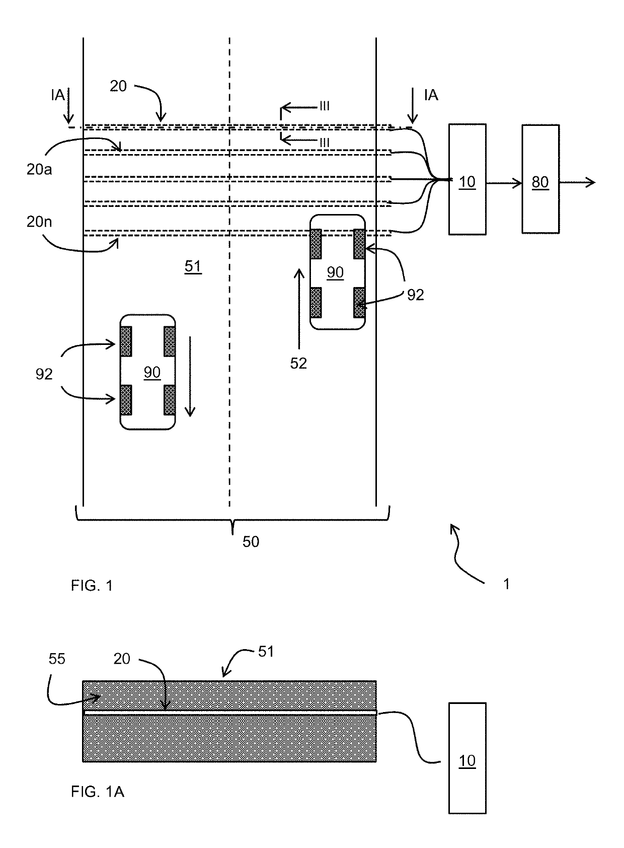
[0104]Experiments were conducted with an experimental implementation of the first embodiment as shown in FIG. 5. The arrangement comprises four fiber optic sensors 20a, 20b, 20c, 20d that are embedded in a road with traffic carrying surface 51. The road has a longitudinal direction indicated by arrow 52. The four fiber optic sensors 20a, 20b, 20c, 20d extend transverse to this direction, i.e. in the lateral direction of the road. The leftmost fiber optic sensors 20a, 20b are embedded close to each other, at a depth of 6 cm below the traffic carrying surface 51 and the rightmost fiber optic sensors 20c, 20d are embedded close to each other, at a depth of 11 cm below the traffic carrying surface 51. The neutral axis of the road used for these experiments was calculated at a depth of about 8.5 cm.

[0105]The two rightmost fiber optic sensors 20c, 20d are arranged at a distance of 1.5 m from the two left-most fiber optic sensors 20a, 20b. The fiber optic sensor 20a has a first longitudina...

second embodiment

[0137]In the second embodiment a plurality of fiber optic sensors 20A, . . . , 20N is provided that are arranged at mutually different longitudinal positions transverse to a longitudinal direction of the road and the plurality of optic strain-sensor elements that are distributed in a longitudinal direction of the road comprise optic strain-sensor elements of respective ones of plurality of fiber optic sensors 20A, . . . , 20N. In this case a first interrogator module 10A provides a detection signal for a strain sensor element of fiber optic sensors 20A, and likewise further interrogator modules up to 10N provide a respective detection signal for a strain sensor element of further fiber optic sensors up to 20N. The properly delayed signals are analogously processed as in the embodiment of FIG. 19B.

[0138]FIG. 20 shows an example of an interrogator 10 providing various signal processing features. The interrogator comprises a conversion module I1 to convert an optic response signal of a...


PUM


Abstract

In an arrangement of a traffic infrastructure and an optic sensor system (10, 20), the traffic infrastructure has a traffic carrying surface (51) for providing support of conveyance elements (92) of a vehicle (90), therewith allowing movements of the vehicle over the traffic carrying surface. The optic sensor system (10, 20) comprising an interrogator (10) and at least one fiber optic sensor (20) arranged below the traffic carrying surface that is coupled to the interrogator. The at least one fiber optic sensor (20) comprising an optic fiber (21) with a plurality of optic strain-sensor elements (22) distributed over its length. The plurality of optic strain-sensor elements (22) have mutually different optical characteristics, e.g. a mutually different characteristic wavelength. The interrogator (10) is configured to transmit an optical interrogation signal into the at least one fiber optic sensor, to receive a response optical signal modulated by said fiber optic sensor, and to identify changes in the optical characteristics of the response optical signal resulting from strains induced in said optic strain-sensor elements as a result of a conveyance element (92) of a vehicle (90) moving over the traffic carrying surface (51) across said at least one fiber optic sensor. wherein the at least one fiber optic sensor (20) extends at least substantially according to a straight line in a direction at least substantially parallel to the traffic carrying surface.

Description

BACKGROUND[0001]The increasing use of traffic infrastructures entails various challenges in the fields of managing traffic and enforcing various regulations on restrictions of vehicles specific roads, as well as planning of maintenance cycles. To address such issues there is a growing need for monitoring of road traffic. The monitoring of traffic requires multiple parameters to be recorded from the roads; size and weight of vehicle, its speed, as well as the deformation each vehicle causes in the road. However, current road monitoring systems involve too many separate electronic measurement elements; induction loops, radars, cameras, and weigh-in-motion systems. This configuration results in an expensive installation with data acquisition units for each unit as well as signal and power connections to each part of the system.[0002]EP2372322 notes that a reduction in the amount of cabling can be achieved by employing optic sensors for example, designed as Fiber Bragg Gratings disposed...

Claims


Application Information

Patent Timeline
Patent Type & Authority Applications(United States)
IPC IPC(8): G01D5/353E01F11/00G08G1/015G08G1/04G08G1/052
CPCG01D5/353E01F11/00G08G1/015G08G1/04G08G1/052
Inventor KARABACAK, DEVREZ MEHMETSINGER, JOHANNES MARIAKNOPPERS, GERMAN ENRIQUEO'DOWD, JOHN
Owner OPTICS11 BV
Why Eureka
Try Eureka