
Broadband electromagnetic wave phase modulating method and meta surface sub-wavelength structure

Inactive Publication Date: 2019-05-09
INST OF OPTICS & ELECTRONICS - CHINESE ACAD OF SCI
View PDF0 Cites 6 Cited by
  • Summary
  • Abstract
  • Description
  • Claims
  • Application Information

AI Technical Summary

Benefits of technology

The present invention has the advantage of producing a single sub-wavelength structure that has a linear phase distribution over a range of 0 to 2π. This structure combines the optical and topological characteristics of sub-wavelength structures. Additionally, it allows for the control of photons in the plane to achieve any phase distribution. Furthermore, this structure works over a wide spectrum range, including infrared, terahertz, and microwave bands. The bandwidth is much larger than traditional structures, making it ideal for the construction of ultra-thin, lightweight optical devices.

Problems solved by technology

In the second, third and fourth techniques as mentioned above, it is usual that one unit structure corresponds to one phase distribution, so the resulting phase distribution is discrete and it is difficult to get a broadband performance.
A traditional amplitude-type diffraction element has high order diffraction, so it is impossible to implement phase control.
The traditional phase-type diffraction optical element implements the phase control by changing the thickness, so that the components are large and heavy and can't meet the requirement of high efficient integration for the current applications.
However, the bandwidth issue of the sub-wavelength structure of the meta-surface structure becomes an important obstacle to its practical application.

Method used


Image

  • Broadband electromagnetic wave phase modulating method and meta surface sub-wavelength structure
  • Broadband electromagnetic wave phase modulating method and meta surface sub-wavelength structure
  • Broadband electromagnetic wave phase modulating method and meta surface sub-wavelength structure

Examples


Embodiment Construction

[0030]Reference will now be made to the embodiments of the present invention, examples of which are illustrated in the accompanying drawings, characterized by like numerals refer to like elements throughout. The following examples of the invention will be described with reference to the accompanying drawings.

[0031]The following description of the present invention will be described in detail with reference to the accompanying drawings, but the scope of the present invention is not limited to the following embodiments, and the following detailed description is intended to be illustrative only and not restrictive. Those skilled in the art will, from one of the following embodiments, implement the entire contents of the claims, those skilled in the art, without departing from the spirit and scope of the invention as defined by the present invention in the context of the protection, many forms may be made, which are within the protection of the present invention.

[0032]According to an as...


PUM


Abstract

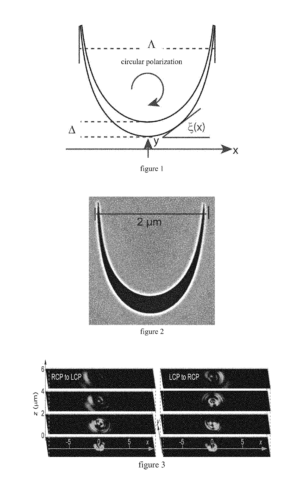
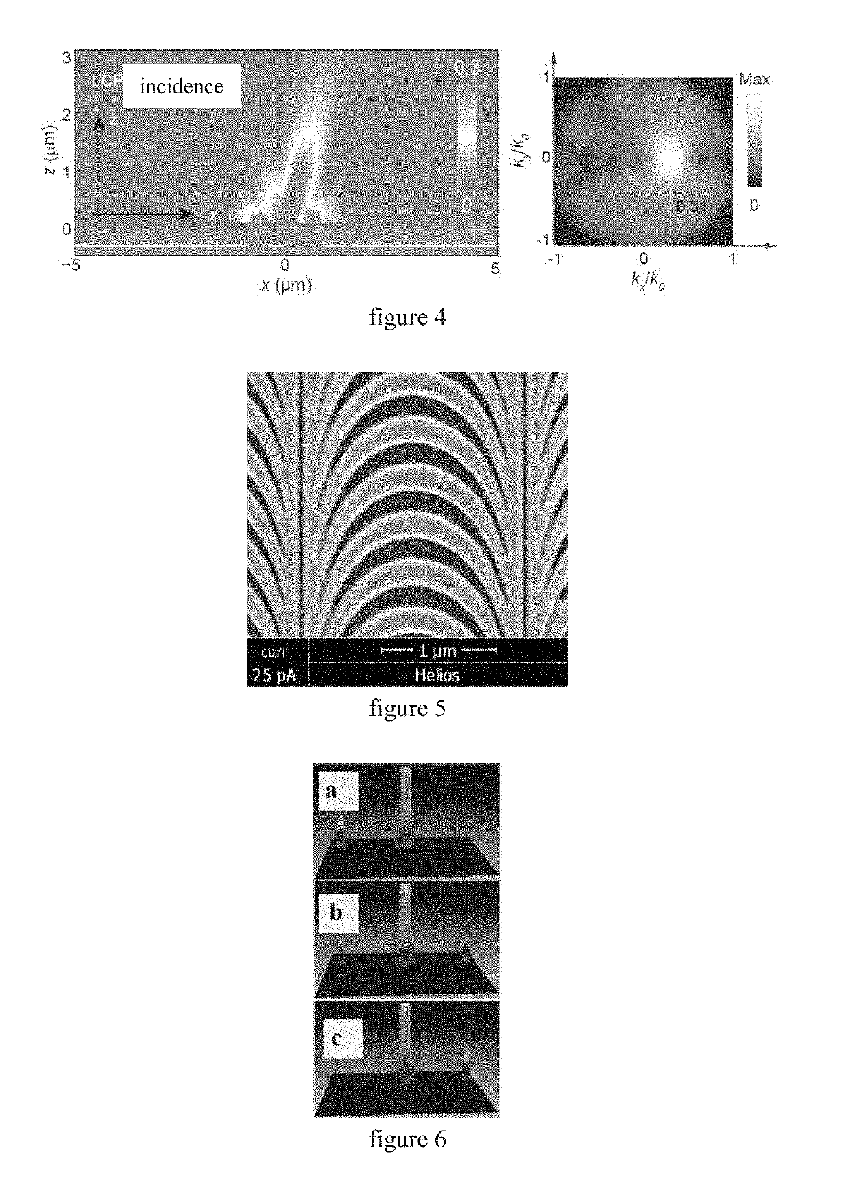
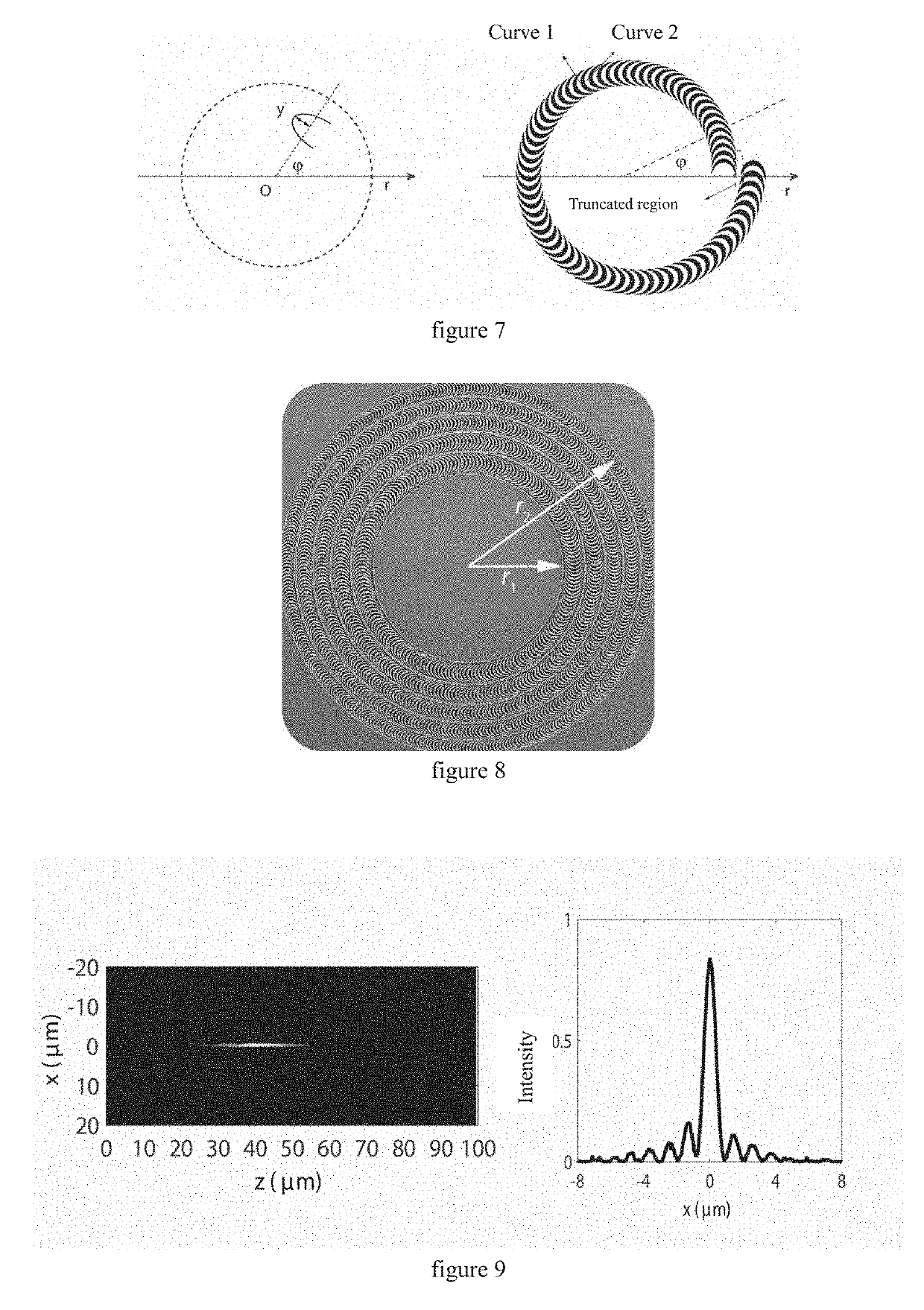
A method for regulating the phase of a wide-band electromagnetic wave uses a meta-surface sub-wavelength structure and the meta-surface sub-wavelength structure. The sub-wavelength structure is used as a basic unit of the meta-surface, and the basic unit is arranged in an array according to a regular order determined by the predetermined phase to generate a geometrical phase distribution with the spatial continuity and the spectral achromaticity between 0 and 2π, so that the phase is controlled and modulated in a two dimensional plane. The operating bandwidth may cover the entire electromagnetic spectrum, and a variety of optical devices such as reflective focusing / imaging elements, transmission focusing / imaging elements, prisms, orbital angular momentum generator may be realized. As an extension of the phase regulation, the method may also realize other novel electromagnetic wave functions such as wideband absorption and radar cross section reduction.

Description

CROSS-REFERENCE TO RELATED APPLICATION(S)[0001]This present application claims priority to a Chinese Application No. 201610249928.2 filed on Apr. 20, 2016 and entitled “BROADBAND ELECTROMAGNETIC WAVE PHASE MODULATING METHOD AND Meta SURFACE SUB-WAVELENGTH STRUCTURE”, which is incorporated herein by reference in their entirety.TECHNICAL FIELD[0002]The present disclosure relates to a field of light field control, and more particularly to a method and a meta-surface sub-wavelength structure for performing wide-band electromagnetic wave phase modulation by using a meta-surface sub-wavelength structure.BACKGROUND[0003]The phase control plays an essential role in various optical components. In particular, in planar photonic devices including planar lenses, beam splitters, prisms and so on, it is a core technology to adjust optical phases in the plane in a range of [0, 360°].[0004]Traditional phase control technologies include the following types.[0005]1. A surface shape and thickness d of...

Claims


Application Information

Patent Timeline
IPC IPC(8): G02F1/01
CPCG02F1/0126G02F2203/50G02F2202/30G02F1/01G02F2203/30G02B1/002G02B5/3083
Inventor LUO, XIANGANGPU, MINGBOZHAO, ZEYULI, XIONGWANG, YANQINMA, XIAOLIANGWANG, CHANGTAO
Owner INST OF OPTICS & ELECTRONICS - CHINESE ACAD OF SCI
Learn More