Ultrasound system and method

Active Publication Date: 2018-02-01
KONINKLJIJKE PHILIPS NV
View PDF3 Cites 2 Cited by
  • Summary
  • Abstract
  • Description
  • Claims
  • Application Information

AI Technical Summary

Benefits of technology

The invention is about a new ultrasound system that uses a special type of transducer called a CMUT. This system can better detect and image noise over a wide range of frequencies. The invention also includes a method for using this system to improve the quality of ultrasound images.

Problems solved by technology

Among these are broad bandwidth, affecting resolution and high sensitivity, which combined with pressure output affects depth of field of acoustic signals at ultrasonic frequencies.
However, PZT suffers from a number of notable drawbacks.
Firstly, the ceramic PZT materials require manufacturing processes including dicing, matching layer bonding, fillers, electroplating and interconnections that are distinctly different and complex and require extensive handling, all of which can result in transducer stack unit yields that are lower than desired.
This manufacturing complexity increases the cost of the final transducer probe and puts design limitations on the minimum spacing between the elements as well as the size of the individual elements.
Moreover, PZT materials have a poorly matched impedance to water or biological tissue, such that matching layers need to be added to the PZT materials in order to obtain the desired acoustic impedance matching with the medium of interest.
As ultrasound system mainframes have become smaller and dominated by field programmable gate arrays (FPGAs) and software for much of the signal processing functionality, the cost of system mainframes has dropped with the size of the systems.
As a result, the cost of the transducer probe is an ever-increasing percentage of the overall cost of the system, an increase which has been accelerated by the advent of higher element-count arrays used for 3D imaging in the case of ultrasound diagnostic imaging systems.
However, such an improved effective bandwidth is not without complications.
Furthermore, the frequency-dependent acoustic speeds of the various frequency components of large bandwidth transmit pulses cause aberrations that can reduce the quality of the wave front, particularly at larger depth.
In addition, using larger bandwidths also means that signal noise, originating from transducer elements and front-end electronics, is integrated over this larger bandwidth and therefore is more prominent.
Next to that, large bandwidth electronic circuits typically dissipate more energy.
Furthermore, signal transfer of the received echo signals across the transducer probe interconnect requires more bandwidth and is therefore more expensive.
However, this prior art citation does not address any of the aforementioned issues associated with low-noise high-bandwidth ultrasound imaging.

Method used


Image

  • Ultrasound system and method
  • Ultrasound system and method
  • Ultrasound system and method

Examples


Embodiment Construction

[0039]It should be understood that the Figures are merely schematic and are not drawn to scale. It should also be understood that the same reference numerals are used throughout the Figures to indicate the same or similar parts.

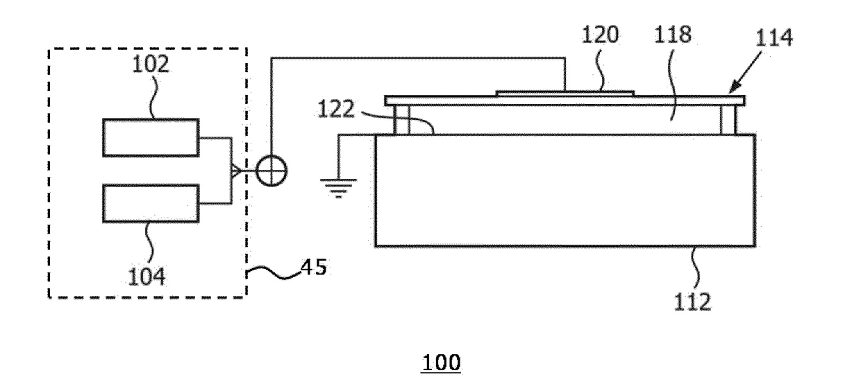
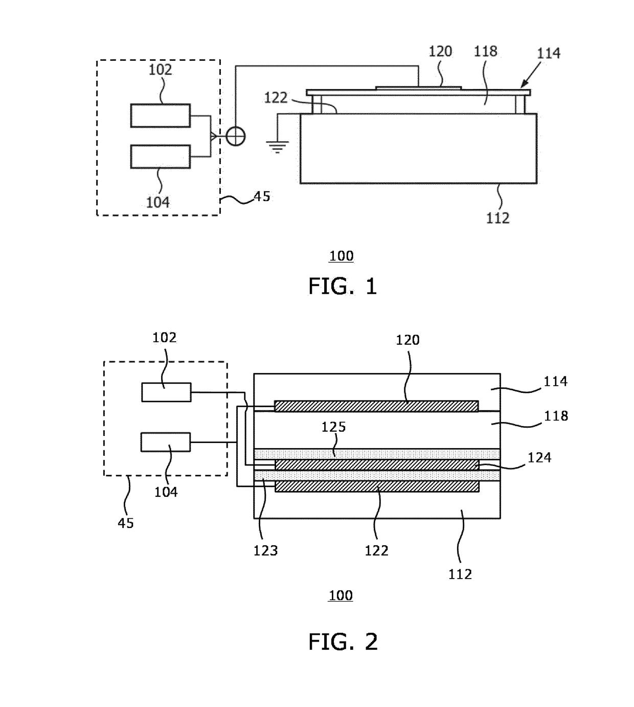
[0040]FIG. 1 shows an aspect of an ultrasound system according to an embodiment, in which the system includes an ultrasound probe having a transducer array comprising CMUT cells 100. As will be explained in further detail below, such an ultrasound system may be an ultrasound diagnostic imaging system in some embodiments or may be an ultrasound therapeutic system in some other embodiments. The present invention is not limited to a particular type of CMUT cells such that any suitable design of CMUT cell 100 may be contemplated. Such a CMUT cell 100 typically comprises a membrane or diaphragm 114 suspended above a silicon substrate 112 with a gap or cavity 118 there between. A top electrode 120 is located on the diaphragm 114 and moves with the diaphragm. A bott...


PUM


Abstract

An ultrasound system (1) is disclosed that comprises a probe (10) including an array (110) of CMUT (capacitive micromachined ultrasound transducer) cells (100), each cell comprising a substrate (112) carrying a first electrode (122) of an electrode arrangement, the substrate being spatially separated from a flexible membrane (114) including a second electrode (120) of said electrode arrangement by a gap (118); a voltage supply (45) coupled to said probe and adapted to provide a first set of said CMUT cells with a sequence of drive voltages each including a bias voltage component and a stimulus component of different frequency for generating a series of temporally distinct pulses each having a different frequency, wherein each pulse is generated in a separate transmit mode and provide a second set of said CMUT cells with a sequence of temporally distinct bias voltages, wherein each temporally distinct bias voltage is provided in a receive mode following one of said transmit modes and is for setting the second set of CMUT cells to a resonance frequency corresponding to the pulse frequency of said transmit mode; and a signal processing unit (22) communicatively coupled to said array and adapted to superimpose the echo signals received by the second set of CMUT cells during the respective receive modes. An ultrasonic imaging method using such a system is also disclosed.

Description

FIELD OF THE INVENTION[0001]The present invention relates to an ultrasound system such as an ultrasound diagnostic imaging system or an ultrasound therapeutic system comprising a probe including an array of CMUT (capacitive micromachined ultrasound transducer) cells, each cell comprising a substrate carrying a first electrode of an electrode arrangement, the substrate being spatially separated from a flexible membrane including a second electrode of said electrode arrangement by a gap; and a voltage supply coupled to said electrode arrangement.[0002]The present invention further relates to an ultrasonic imaging method using such a system.BACKGROUND OF THE INVENTION[0003]Ultrasonic transducers used for medical imaging have numerous characteristics that lead to the production of high quality diagnostic images. Among these are broad bandwidth, affecting resolution and high sensitivity, which combined with pressure output affects depth of field of acoustic signals at ultrasonic frequenc...

Claims


Application Information

Patent Timeline
IPC IPC(8): B06B1/02G01N29/24A61B8/00
CPCB06B1/0215B06B1/0292A61B8/4483G01N29/2406A61B8/12A61B8/4494
Inventor VAN RENS, ANTONIA CORNELIA
Owner KONINKLJIJKE PHILIPS NV
Why Eureka
Try Eureka