Method of operation a differential protection scheme

a protection scheme and differential protection technology, applied in the direction of emergency protection arrangement details, time-division multiplex, electrical apparatus, etc., can solve the problems of not being practicable to employ a reconfigurable differential protection scheme based on direct, damage to the electrical power network, etc., to achieve cost and complexity, increase or decrease the number of terminals, the effect of easy scaling

Active Publication Date: 2019-05-09
GENERAL ELECTRIC TECH GMBH
View PDF2 Cites 0 Cited by
  • Summary
  • Abstract
  • Description
  • Claims
  • Application Information

AI Technical Summary

Benefits of technology

[0010]As set out above, the communications network is any one of: a daisy-chain communications network; a ring communications network; a meshed communications network; a star communications network; a bus communications network; a tree communications network; or a hybrid thereof. The communications protocol employed by such a communications network allows the reconfiguration information to be communicated among the plurality of terminals in the same way (e.g. by way of transmission of an identical message) regardless of the number of terminals. In addition the topology of such a communications network means that it is straightforward to increase or decrease the number of terminals in the communications network. As a result, the provision of such a communications network to communicate the reconfiguration information among the plurality of terminals renders the method of the invention readily scalable to accommodate any number of terminals (e.g. 3, 4, 5, 6 or more) in the electrical power network, while at the same time obviating the need for any substantial redesign in terms of communications protocol and hardware.
[0011]Furthermore, the provision of such a communications network to communicate the reconfiguration information among the plurality of terminals in the method of the invention removes the need for direct point-to-point communication between the plurality of terminals whereby each terminal is required to be directly connected, via direct point-point communication links, to each of the other terminals. More so, it would not be practical to employ a reconfigurable differential protection scheme based on direct point-to-point communication between the plurality of terminals in an electrical power network with more than 3 terminals, due to the cost and complexity in implementing direct point-point communication links between the terminals. By way of example, where 6 is the number of terminals, direct point-to-point communication between the plurality of terminals requires 30 communication links, whereas the communications network of the invention requires significantly fewer than 30 communications links, e.g. a ring communications network based on 6 terminals only requires 6 communication links between the plurality of terminals.
[0031]These steps may be included in the method of the invention to ensure that the reconfiguration of the differential protection scheme can still take place in the event of failure of one of the plurality of terminals of the electrical power network. The communications protocol employed by the communications network allows the reconfiguration information to be readily communicated to the substitute terminal that is newly added to the communications network, without requiring a substantial redesign of the communications protocol. In addition the topology of the communications network means that it is straightforward to replace the failed terminal with the substitute terminal in the communications network.

Problems solved by technology

Otherwise failure to reconfigure the differential protection scheme under such circumstances could result in errors in the differential protection of the electrical power network and thereby could damage the electrical power network.
More so, it would not be practical to employ a reconfigurable differential protection scheme based on direct point-to-point communication between the plurality of terminals in an electrical power network with more than 3 terminals, due to the cost and complexity in implementing direct point-point communication links between the terminals.

Method used


Image

  • Method of operation a differential protection scheme
  • Method of operation a differential protection scheme
  • Method of operation a differential protection scheme

Examples


first embodiment

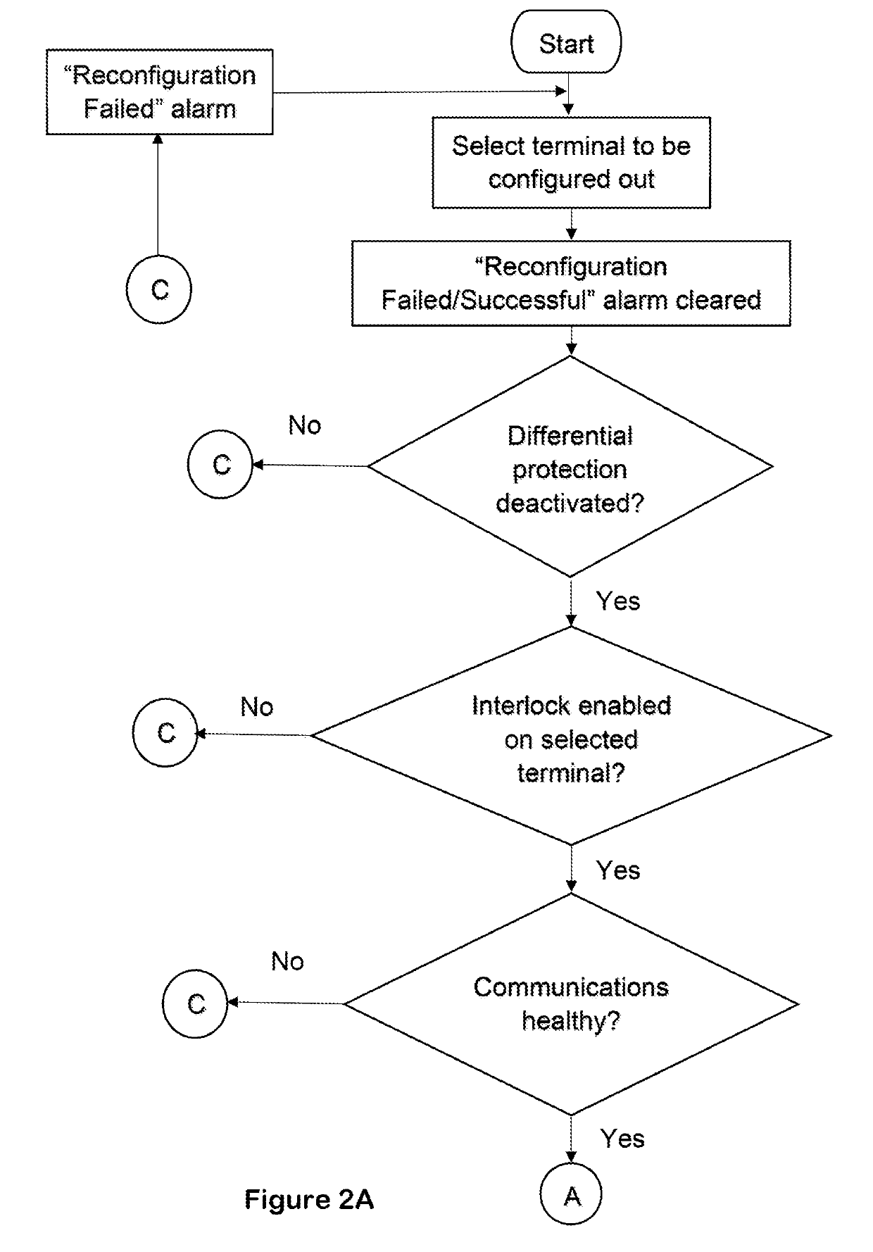
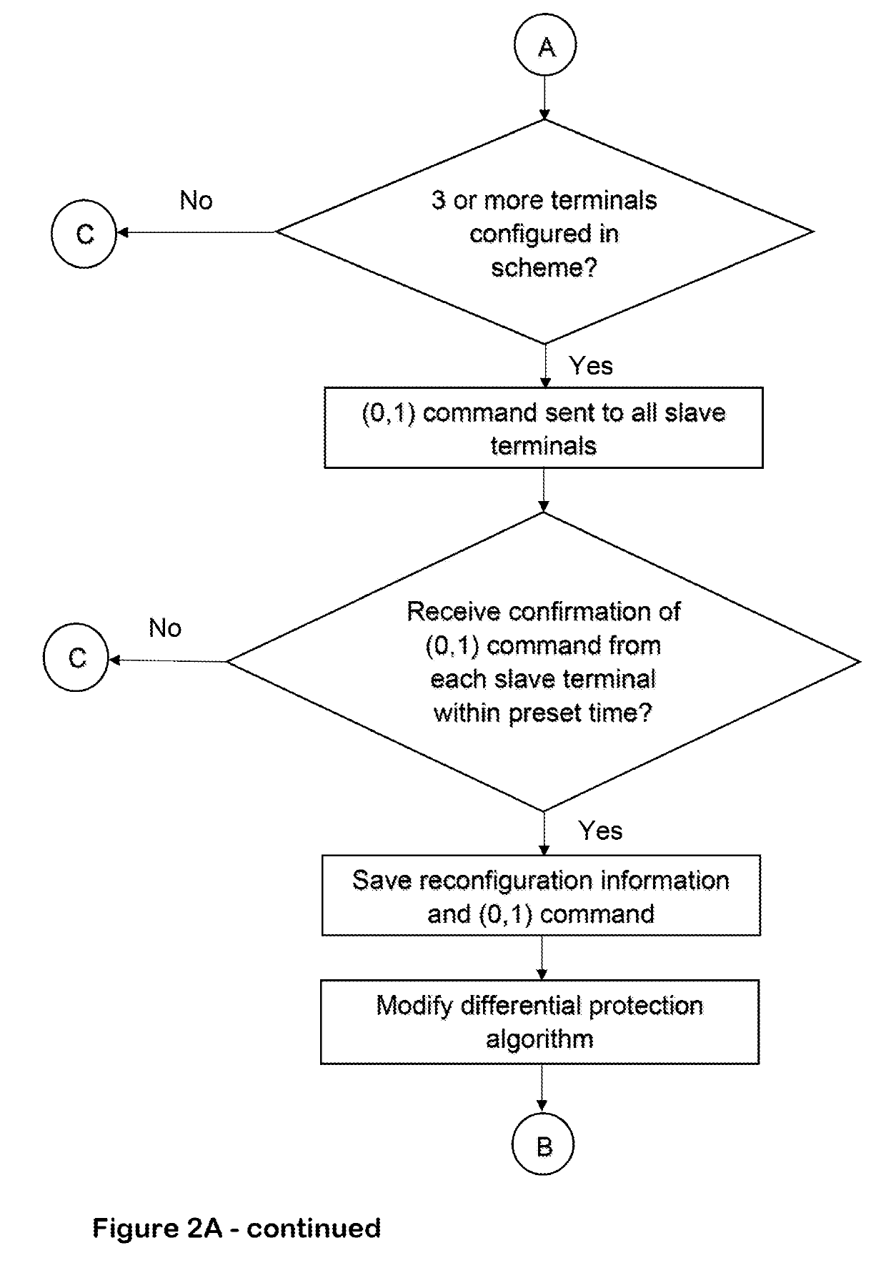
[0056]A method according to the invention reconfigures the differential protection scheme by configuring a selected terminal out of or into the differential protection scheme.

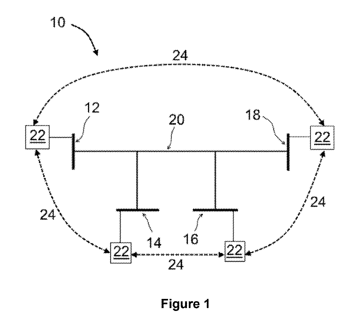
[0057]Control data is saved locally in the control unit 22 of each terminal 12, 14, 16, 18. The method of the first embodiment of the invention involves the transmission of the control data in an identical message among the terminals 12, 14, 16, 18 via the ring communications network, which permits the reconfiguration of the differential protection scheme to be carried out by accessing the control unit 22 of a local terminal. For ease of reference, the local terminal is referred to hereon as a master terminal, while the other terminals are referred to hereon as slave terminals.

[0058]In the method according to the first embodiment of the invention, the terminal 12 is designated as the master terminal, while the other terminals 14, 16 and 18 are designated as slave terminals. It will be appreciated that any of th...

second embodiment

[0115]A method according to the invention reconfigures the differential protection scheme by configuring a selected terminal out of the differential protection scheme, with the addition of steps of replacing a failed terminal being replaced by a substitute terminal.

[0116]For the purposes of illustrating the working of the method according to the second embodiment of the invention, the terminal 16 is designated as the failed terminal to be replaced, but it will be appreciated that the method according to the first embodiment of the invention applies mutatis mutandis to any of the other terminals 12, 14, 18 as the failed terminal to be replaced.

[0117]The functions of the master terminal 12 and the slave terminals 14, 18 in the method according to the second embodiment of the invention are identical to the functions of their counterparts in the method according to the first embodiment of the invention, with reference to FIGS. 2A, 2B, 3A and 3B.

[0118]The additional steps of replacing a ...


PUM


Abstract

There is provided a method of operating a reconfigurable differential protection scheme for carrying out differential protection of an electrical power network, the electrical power network comprising terminals, each of the terminals configured to be in communication with each other within a communications network. The method includes controlling the differential protection scheme to deactivate the differential protection, and selecting a terminal to be configured out of or into the differential protection scheme. The method also includes communicating reconfiguration information among the terminals, the reconfiguration information including the selection of the terminal to be configured out of or into the differential protection scheme. The method also includes modifying a respective differential protection algorithm at each of the non-selected terminals so as to configure the selected terminal out of or into the differential protection scheme, and controlling the differential protection scheme to reactivate the differential protection.

Description

BACKGROUND[0001]This invention relates to a method of operating a differential protection scheme, and to an electrical power network comprising a differential protection scheme.[0002]Current differential protection schemes help to protect transmission lines within an electrical power system by identifying when a fault occurs in relation to the transmission lines. The basic principle of current differential protection is based on a calculation of a difference between the currents entering and leaving a protected zone. Tripping of a local circuit breaker is carried out when the difference exceeds a set trip threshold. In addition to tripping the local circuit breaker, a local terminal sends an intertrip signal to the remote terminals to ensure tripping at all ends of the protected zone.BRIEF SUMMARY[0003]According to a first aspect of the invention, there is provided a method of operating a reconfigurable differential protection scheme for carrying out differential protection of an el...

Claims


Application Information

Patent Timeline
Patent Type & Authority Applications(United States)
IPC IPC(8): H02H7/26H02H1/00H02H3/30H02J13/00H04J3/06
CPCH02H7/261H02H1/0061H02H3/30H02J13/0013H04J3/0641H02H3/28Y04S40/12H02J13/00006H02J13/0004Y02E60/00H04J3/0638H02J13/00
Inventor WESTWOOD, JOHNZHANG, YANZHONG
Owner GENERAL ELECTRIC TECH GMBH
Why Eureka
Try Eureka