Simulation system and game system

a simulation system and game technology, applied in the field of simulation systems, can solve problems such as difficulty in simulating a situation that seems real, and achieve the effects of ensuring smooth movement and safety of players, preventing situations, and ensuring safe movemen

Active Publication Date: 2019-05-16
BANDAI NAMCO ENTERTAINMENT INC
View PDF2 Cites 7 Cited by
  • Summary
  • Abstract
  • Description
  • Claims
  • Application Information

AI Technical Summary

Benefits of technology

[0090]Since the invention is configured so that the wearable image display device is hanging, it is possible to ensure that the wearable image display device is continuously worn by the user and does not fall when the user removes the wearable image display device, even when the user loses balance or when the user loses balance and unintentionally falls down as a result of moving in the user movement space or the wearable image display device being put on.
[0091]Accordingly, the invention can prevent an unexpected situation in which the user is injured when the user has fallen down while wearing the wearable image display device, or the wearable image display device collides with the floor or a wall surface due to unintentional removal, and breaks or malfunctions, for example.
[0092]Since the invention is configured so that the wearable image display device can be hung at a suitable position, and can move or make a motion in an arbitrary direction as long as the hanging position of the wearable image display device can be changed using a rail, an arm, or the like so as to follow the movement of the user, for example, it is possible to ensure that the user wearing the wearable image display device can safely move in the real space, prevent a situation in which the user is injured, and prevent an unexpected situation in which the wearable image display device breaks or malfunctions, for example.
[0093]For example, when an image is supplied to the wearable image display device through a cable, or the wearable image display device is controlled through a cable (e.g., when a high-resolution image is used), it is possible to provide a line that connects the wearable image display device and a control device that controls the wearable image display device through the hanging unit. As such, it is possible to prevent a situation in which the movement of the user is limited, or the user feels uncomfortable due to the presence of the line that is situated on the side of the user, or around the feet of the user.
[0094]Specifically, the above configuration makes it possible for the invention to ensure smooth movement and safety of the player P wearing the wearable image display device in the user movement space, and prevent unexpected situations such as the user being injured.

Problems solved by technology

However, with the simulation system described in PTL 1, the situation of the user in virtual space is not simulated in correspondence with the movement and / or state of the user in real space.
Consequently, it is difficult to simulate a situation that seems real and provide the user with a realistic experience.

Method used


Image

  • Simulation system and game system
  • Simulation system and game system
  • Simulation system and game system

Examples


modification examples

5. MODIFICATION EXAMPLES

5-1 Modification Example 1

[0457]In the embodiment described above, a case is described in which the simulation process in the simulation space was implemented as a game, but the invention may be implemented as a simulator that is unrelated to a game.

modification example 2

5-2 Modification Example 2

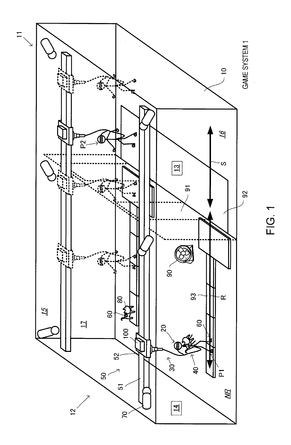
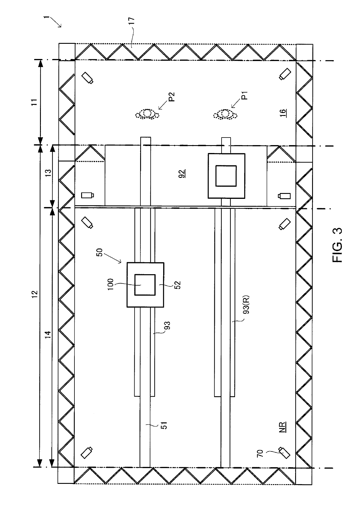
[0458]In the embodiment described above, a case is described in which the player's state is detected by using the marker unit 60 and the imaging camera 70, but a configuration is possible in which the player's state is detected using a sensor unit (e.g., contact sensor) placed on the moving path R or the non-moving path NR.

[0459]For example, in such a configuration, the state detection processing section 112 determines that the player P is at the position of the sensor unit when he player P is detected by the sensor unit placed on the moving path R.

[0460]Alternatively, a configuration is possible in which, when the player P is detected by a sensor unit placed on the non-moving path NR, the state detection processing section 112 detects that the player P has run off the moving path at the position of that sensor unit, and detects the game termination due to the player P failing to move along the moving path.

[0461]A configuration is possible in which, in the ...

modification example 3

5-3 Modification Example 3

[0463]In the embodiment described above, a case is described in which the hanging control unit 50 is formed from the one rail 51 and the sliding member 52 that slides along the rail 51, but a configuration is possible in which the hanging control unit 50 is formed from rails along two or three axes and the sliding member 52 (see FIG. 15A). Additionally, a configuration is possible in which, instead of a rail, the hanging control unit 50 is formed from an arm capable of three-dimensionally hanging the hanging control unit 50 (see FIG. 15B).

[0464]Note that FIG. 15A and FIG. 15B are drawings illustrating modification examples of the hanging control unit 50 of the present embodiment. More specifically, FIG. 15A illustrates an example of the hanging control unit 50 wherein rails along two axes and a sliding member are formed, and FIG. 15B illustrates an example of a hanging control unit 50 formed from an arm capable of three-dimensionally hanging the hanging uni...


PUM


Abstract

A game system 1 is configured to detect a player's state (i.e., the position and the attitude of the player in the real space) that represents the state of the player P in the real space, perform an image generation process that generates a simulation image corresponding to the detected player's state, the simulation image being viewed from the player P and representing the simulation space that corresponds to the real space, the simulation image including a virtual moving path that is linked to a moving path R, display the generated simulation image on the HMD 20, determine that the player P is in a specific state in the simulation space when the player's state has satisfied a given condition within the moving path R, and generate a simulation image that produces an effect based on the specific state when it has been determined that the player P is in the specific state.

Description

TECHNICAL FIELD[0001]The present invention relates to a simulation system that utilizes a wearable image display device such as a head-mounted display.BACKGROUND ART[0002]In the related art, there are wearable image display devices that are worn by and display images to a user. Head-mounted displays (HMD) are examples of such devices. HMDs are generally divided into monocular and biocular devices and are further classified into non-see-through type devices and see-through type devices. In non-see through type devices, vision is secured in the movement space in which the user is actually moving (that is, real space). In see-through type devices, each eye of the user is masked (that is, completely covered) and images linked to the real space are displayed.[0003]Recently, technologies have been proposed for game devices configured as simulation systems that display predetermined images on such an HMD (for example, JP-A-2015-150063). In such technologies, the field-of-view of the user i...

Claims


Application Information

Patent Timeline
Patent Type & Authority Applications(United States)
IPC IPC(8): A63F13/80A63F13/285G06T19/00G02B27/01H04N13/344A63F13/213G06F3/01
CPCA63F13/80A63F13/285G06T19/003G02B27/0172H04N13/344A63F13/213G06F3/011G02B2027/0138G02B2027/014A63F2300/8082G09B9/00A63F13/428A63F13/90A63F13/52A63F13/28A63F13/55A63F13/26A63F13/212A63F13/27G09B19/00G09B19/0038A63F13/25
Inventor TAMIYA, YUKIHARUNISHIMURA, NORIHIRO
Owner BANDAI NAMCO ENTERTAINMENT INC
Why Eureka
Try Eureka