Display driver, electro-optical device, and electronic apparatus

a technology of electrooptical devices and electronic devices, applied in the direction of instruments, static indicating devices, etc., can solve the problems of difficulty in achieving a high gain over the entire fluctuation range of bias points, and the related arts have not made any artifices or devices for achieving multiple gradations

Active Publication Date: 2019-05-16
SEIKO EPSON CORP
View PDF0 Cites 3 Cited by
  • Summary
  • Abstract
  • Description
  • Claims
  • Application Information

AI Technical Summary

Benefits of technology

The invention relates to a display device that can output multiple gradations for a given set of data. The device uses an inverting amplifier circuit that can output the reference voltage based on the lower-bit data of the display data. The upper-bit data is converted into a gradation voltage by a D / A converter circuit and then amplified using the inverting amplifier circuit. The output voltage of the inverting amplifier circuit is then divided by a reference voltage that is output based on the lower-bit data. This allows for a larger number of gradations to be achieved. The invention also includes current compensating circuits to reduce errors in the gradation voltage output. The technical effect of the invention is to provide a display device that can output multiple gradations for a given set of data.

Problems solved by technology

Thus, it is difficult to achieve a high gain over the entire fluctuation range of the bias point.
Unfortunately, in a case where an inverting amplifier circuit is adopted as the amplifier circuit as described above, the related arts have not made any artifice or device for achieving multiple gradations.

Method used


Image

  • Display driver, electro-optical device, and electronic apparatus
  • Display driver, electro-optical device, and electronic apparatus
  • Display driver, electro-optical device, and electronic apparatus

Examples


Embodiment Construction

[0043]Some exemplary embodiments of the invention will be described in detail hereinafter. Note that the exemplary embodiments described hereinafter are not intended to limit the content of the invention as set forth in the claims, and not all of the configurations described in the exemplary embodiments are absolutely required to address the issues described in the invention.

[0044]1. First Configuration Example of Display Driver

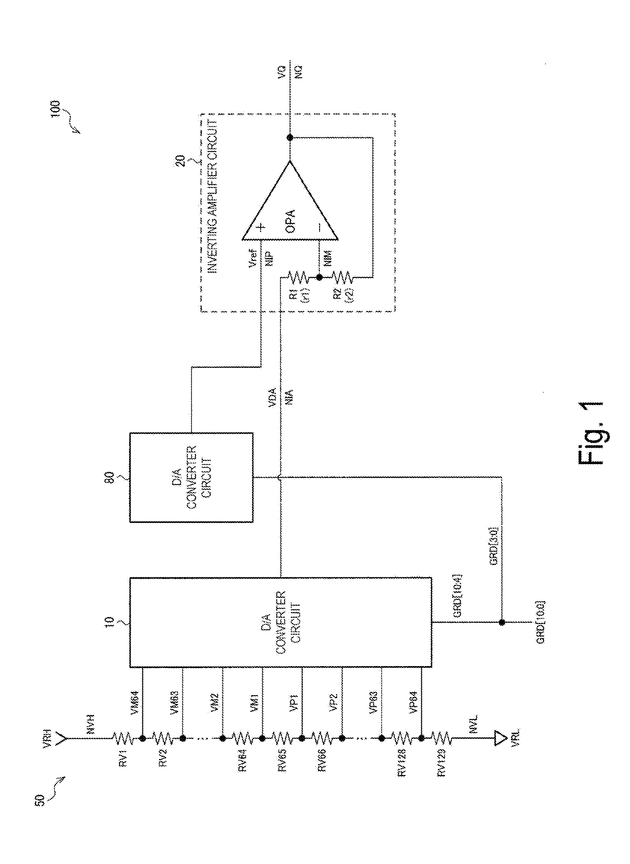
[0045]FIG. 1 is a first configuration example of a display driver 100 of the exemplary embodiment. The display driver 100 includes a digital-to-analog (D / A) converter circuit 10 (first D / A converter circuit), an inverting amplifier circuit 20, and a digital-to-analog (D / A) converter circuit 80 (second D / A converter circuit). The display driver 100 may further include a ladder resistance circuit 50 (gradation voltage generating circuit). Note that the exemplary embodiment is not limited to the configuration in FIG. 1, and various modifications can be achieved ...


PUM


Abstract

A display driver includes a first digital-to-analog (D / A) converter circuit configured to convert upper-bit data of display data into a gradation voltage corresponding to the upper-bit data, a second digital-to-analog (D / A) converter circuit configured to output a reference voltage that is varied in accordance with lower-bit data of the display data, and an inverting amplifier circuit configured to amplify the gradation voltage with reference to the reference voltage and to drive a data line of an electro-optical panel.

Description

BACKGROUND1. Technical Field[0001]The invention relates to a display driver, an electro-optical device, and an electronic apparatus.2. Related Art[0002]A display driver for driving an electro-optical panel includes a ladder resistance circuit for generating a plurality of voltages, a digital-to-analog (D / A) converter circuit for selecting a gradation voltage corresponding to display data from the plurality of voltages, and an amplifier circuit for amplifying or buffering (executing impedance conversion on) the gradation voltage. A related technology of such a display driver is disclosed in, for example, JP-A-2005-292856, JP-A-2001-67047, and JP-A-10-260664.[0003]In JP-A-2005-292856, the amplifier circuit is formed of a forward amplifier circuit. That is, a gradation voltage is input to a non-inverting input terminal (positive terminal) of an operational amplifier, and a feedback voltage is input to an inverting input terminal (negative terminal).[0004]In JP-A-2001-67047 and JP-A-10-...

Claims


Application Information

Patent Timeline
Patent Type & Authority Applications(United States)
IPC IPC(8): G09G3/20
CPCG09G3/2011G09G2310/027G09G2310/0291G09G2320/0673G09G2330/028G09G3/20G09G3/3685
Inventor MORITA, AKIRA
Owner SEIKO EPSON CORP
Why Eureka
Try Eureka