
Process for over-moulding an outer stator

Active Publication Date: 2019-05-16
DEMAK
View PDF0 Cites 3 Cited by
  • Summary
  • Abstract
  • Description
  • Claims
  • Application Information

AI Technical Summary

Benefits of technology

The present invention provides a method for coating a stator with resin that has faster and easier control over previous methods. The method allows the stator to be separated from the still hot core without waiting for the core to cool and shrink. The core can be deflated and removed from the stator quickly, reducing the risk of scratches and abrasions and allowing the core to be used for a high number of working cycles, reducing the cost of the coating method.

Problems solved by technology

Otherwise, the functionality of the motor will be compromised, unless long and complex resin removal methods are subsequently carried out on parts on which resin has been improperly poured and which are intended to house the rotor.
However, the time required for the cooling process to occur spontaneously is rather long and thus economically incompatible with an industrial working cycle.
Consequently, it is necessary to conduct a forced cooling process with the risk that it will produce fissures, cracks, etc. in the resin coating.
Moreover, the separation operation requires applying a significant mechanical force, which can cause scratches and abrasions to form on the core's outer surface.
Therefore, after a few working cycles, the core has an outer surface so damaged as to be useless and in need of replacement.

Method used


Image

  • Process for over-moulding an outer stator
  • Process for over-moulding an outer stator
  • Process for over-moulding an outer stator

Examples


Embodiment Construction

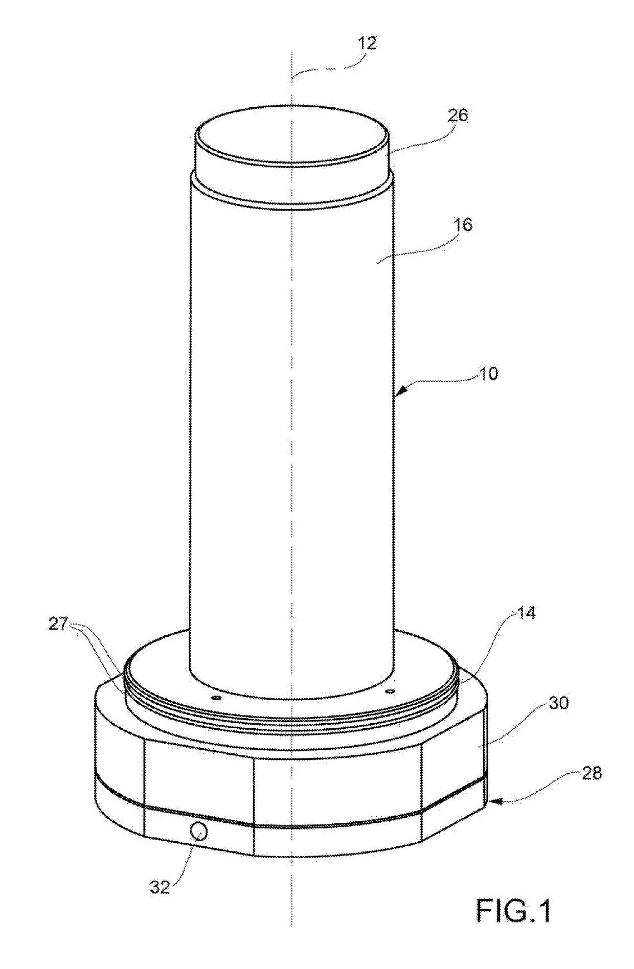
[0014]A core 10 for undertaking a resin coating method is configured symmetrically (FIG. 1) with respect to a central longitudinal axis 12 and has a disc-shaped lower portion 14 and an upper cylindrical portion 16 that protrudes from a central zone of a surface facing upward of the lower portion 14. Both portions 14 and 16 have circular cross-sections.

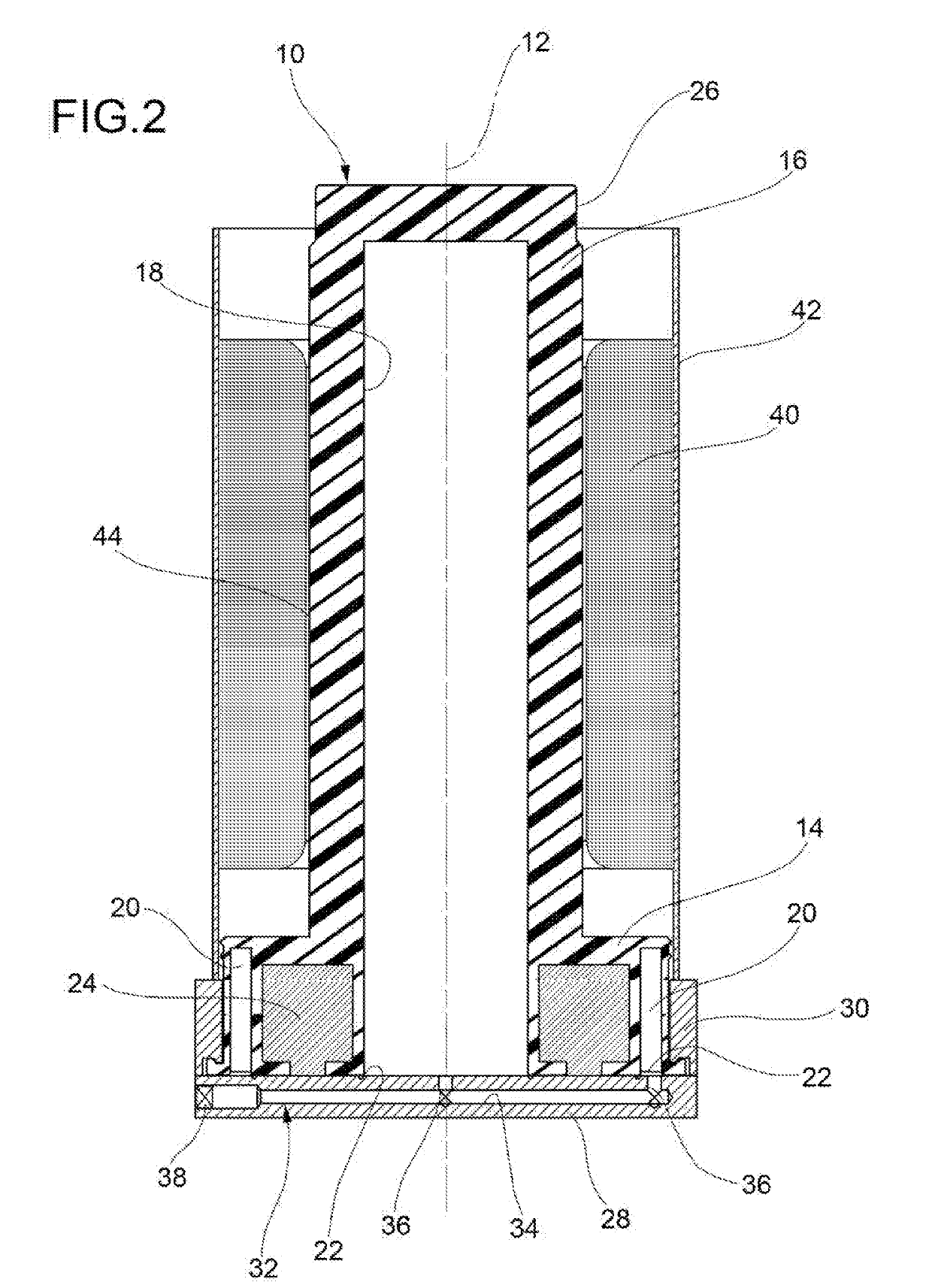
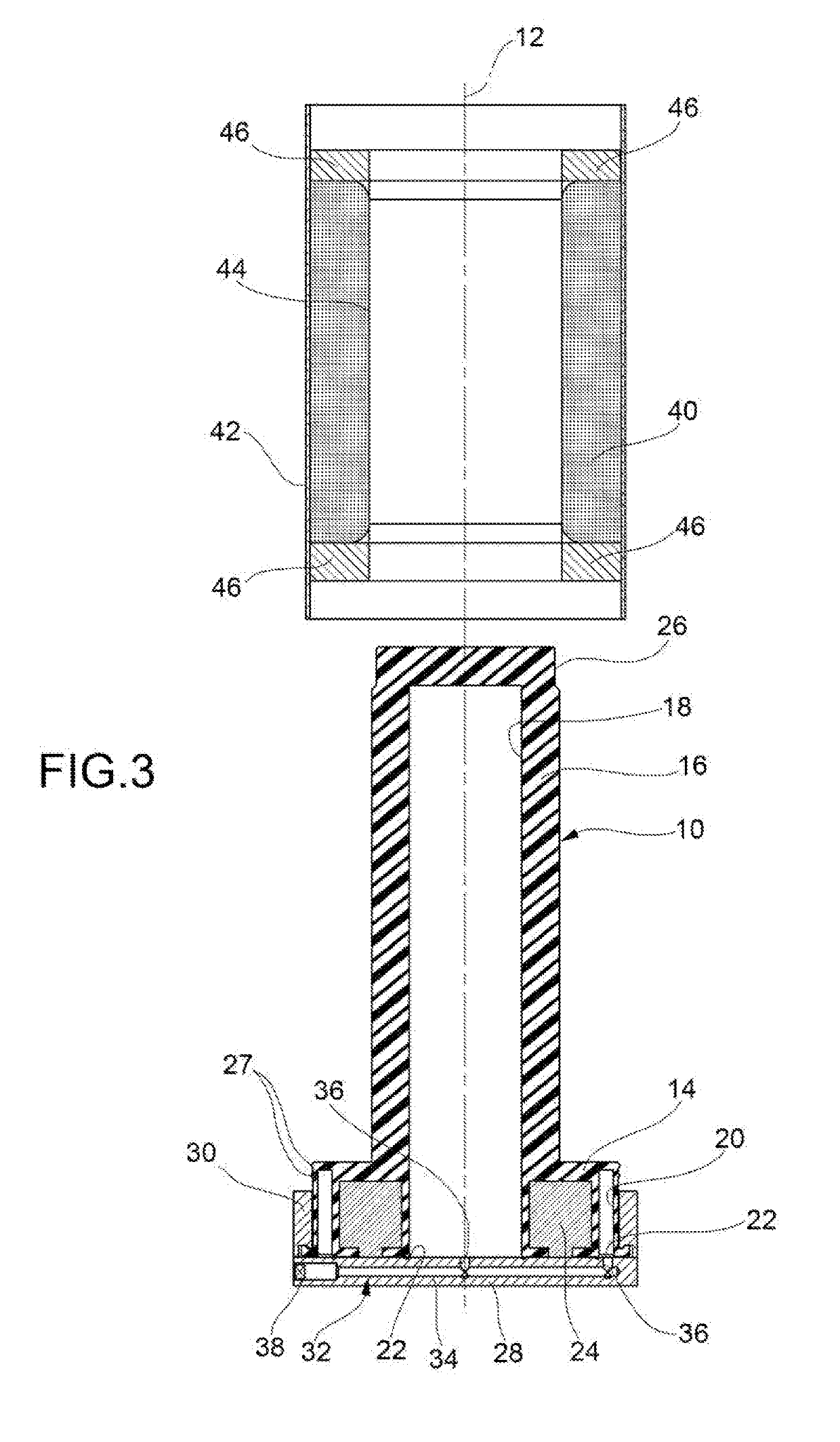
[0015]The core 10 has an elastic wall, for example of silicone rubber, which encloses a first inner chamber 18 of cylindrical shape and with a circular cross-section, arranged centrally and extending through the upper and lower portions 14, 16, and a second inner chamber 20 having a ring shape and extending in a peripheral region of the lower portion 14 coaxially outside the lower end of the first chamber 18. Chambers 18, 20 respectively have openings 22 toward the lower side.

[0016]The wall of the lower portion 16 also surrounds a metal ring 24 arranged coaxially within the second chamber 20 and the outside of the lower end of the firs...


PUM

PropertyMeasurementUnit
Timeaaaaaaaaaa
Shapeaaaaaaaaaa

Abstract

A method for resin coating electrical windings enclosed within a housing of an electric motor and defining a central cylindrical cavity, the method including preparing a core having an elastic wall that encloses an inner chamber having an opening provided with a selective shut-off means, as well as a lower disc-like portion and an upper cylindrical portion that protrudes from a surface of the lower portion, coupling the core and an electric motor stator, in such a way that the upper portion occupies the cavity of the stator, and the lower portion is positioned within a housing of the motor below the electric windings, inflating the inner chamber through the opening, in such a way that the lower portion comes into contact with an inner surface of the housing and the upper portion comes into contact with the windings, which define a central cavity of the stator, pouring a resin so that it coats the windings when they are not in contact with the core; deflating through the opening the inner chamber, and separating the core from the stator, whose windings are coated with resin.

Description

TECHNICAL FIELD[0001]The present disclosure relates to a method for embedding in a two-component resin electrical windings enclosed within the housing of an electric motor stator having a central cylindrical cavity in which is housed the related rotor.BACKGROUND[0002]This method is typically conducted in an oven, after pouring liquid, two-component resin on the windings where it cures, forming a solid layer of coating. It is therefore critical to ensure that the resin only comes in contact with the parts of the windings that are to be actually embedded. Otherwise, the functionality of the motor will be compromised, unless long and complex resin removal methods are subsequently carried out on parts on which resin has been improperly poured and which are intended to house the rotor.[0003]Therefore, according to a known technique, prior to pouring the resin, a core of a material having a thermal expansion coefficient higher than that of the stator material is inserted within the centra...

Claims


Application Information

Patent Timeline
IPC IPC(8): H02K15/12B29C33/50B29C39/10H02K5/08
CPCH02K15/12B29C33/505B29C39/10H02K5/08H02K15/02Y10T29/49009
Inventor GASTALDI, MAURIZIO
Owner DEMAK
Learn More