Plunger Pump Fluid End

a technology of fluid end and pump, which is applied in the direction of positive displacement liquid engine, piston pump, liquid fuel engine, etc., can solve the problems of fluid end failure frequently, excessive stress and failure, and fluid end failure to fatigue, so as to improve the durability and improve the fatigue life

Active Publication Date: 2019-05-23
ADVANCED UPSTREAM SOLUTIONS LLC
View PDF0 Cites 19 Cited by
  • Summary
  • Abstract
  • Description
  • Claims
  • Application Information

AI Technical Summary

Benefits of technology

[0009]The preferred embodiment of the fluid end design of the present invention distributes peak applied stresses in a manner that reveals significantly improves durability over the typical industry fluid end. Test results with internal fluid end pressure at 15,000 psi indicate that peak stress reduction for the instant design translates into an improvement in fatigue life of the fluid end of over 200% when compared to a typical industry fluid end made of the same alloy materials. This increased life provides the instant design significant reductions in the rates of crack initiation and propagation. On a relative basis, the instant design's internal bore profile demonstrated peak stresses during testing that were 24.4% lower when compared to the typical industry design with identical material properties:

Problems solved by technology

A common problem associated with operating these types of reciprocating pumps at alternating high and low pressures is fatigue failure in the fluid end, particularly in areas where because of internal geometries there are high stress concentrations, including areas near the fluid chambers and near the suction and discharge valves.
The area where the four bores previously described generally intersect at a fluid chamber experience excessive stresses and failures by fatigue cracks.
Fluid end failure frequently occurs when there is a stress fracture, followed by a washout between the discharge bore cavity and the pumping chamber.
This results in an enormous loss of pump efficiency.
As the plunger in such a compromised fluid end draws back it draws in fluid from the discharge cavity and pushes it back out, resulting in a highly diminished pump output.
Another area of stress concentration, risk of fatigue cracking and erosion in fluid ends occurs near the valves.
Each bore in the fluid end housing is subject to fatigue due to the pressures that occur during pump cycling.
In addition, the circumferential areas of the fluid end housing across from the valve openings are prone to erosion risk due to high concentrations and velocities of fluid flow through the suction and discharge valves.
Turbulent fluid flow patterns may lead to vibrations in the pump.
Furthermore, fracking fluid travels at high pressures out of valves and erodes the walls of the bores.
Because of the extremely harsh operating conditions imposed upon them, despite the best materials and designs, fluid end internals and housings must be frequently serviced and repaired or replaced.
Both of these prior art retainer configurations, however, include geometries, parts and orientations which create additional stresses within the suction bore that can require and reduce the life of the fluid end and pump and prove more difficult and time consuming to service.

Method used


Image

  • Plunger Pump Fluid End
  • Plunger Pump Fluid End
  • Plunger Pump Fluid End

Examples


Embodiment Construction

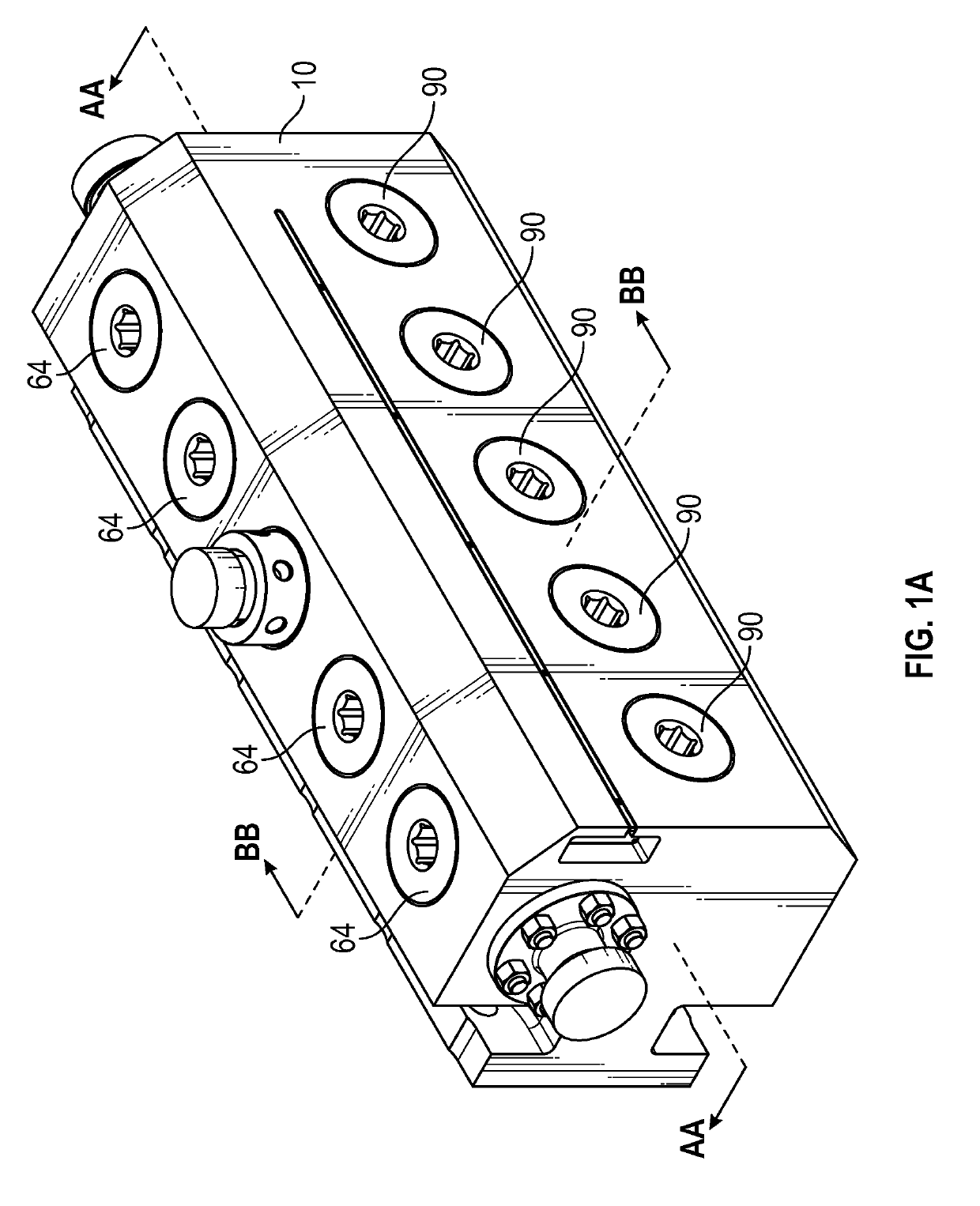
[0041]FIG. 1A is representative embodiment of a reciprocating plunger pump fluid end housing 10 of the present invention. Lines AA and BB are referenced for orientation purposes in additional drawings.

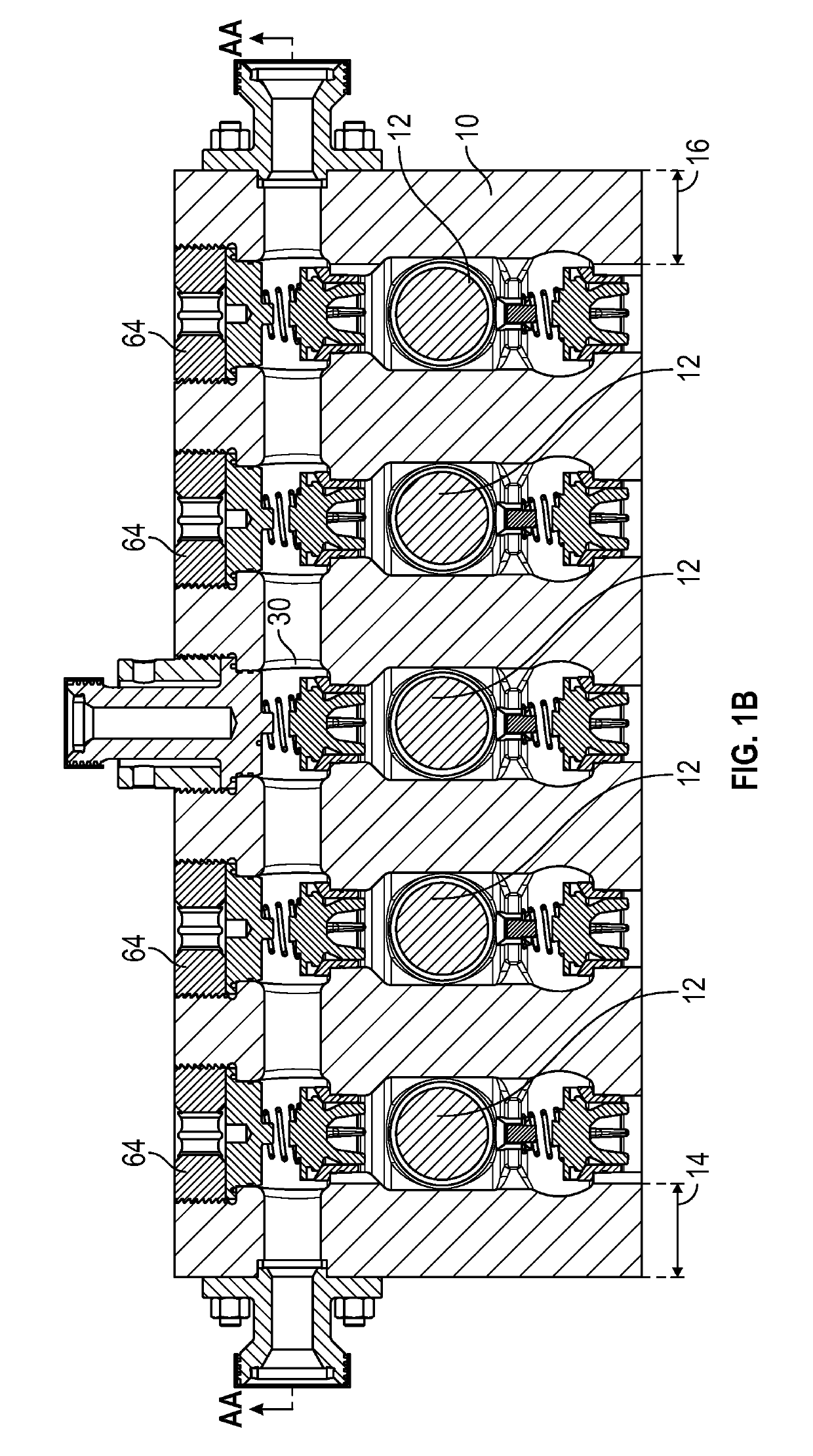
[0042]FIG. 1B is a cross-sectional view of the fluid end 10 of the present invention through line BB in FIG. 1. In the depicted embodiment, the fluid end 10 is a quintuplex pump, having five plunger cylinders 12. However, such pumps may have any appropriate number of cylinders, such as a three-cylinder pump (triplex pump). In one embodiment, the fluid end 10 has additional wall thickness to the sides (14 and 16) of the two outer cylinder bores 12 in comparison to corresponding areas in prior art fluid ends to reduce stress in the more stress vulnerable areas of the fluid end block. In the exemplary design in FIG. 1B the wall thickness at 14 and 16 is 4.25 in., compared to a typical industry standard 3.375 in.

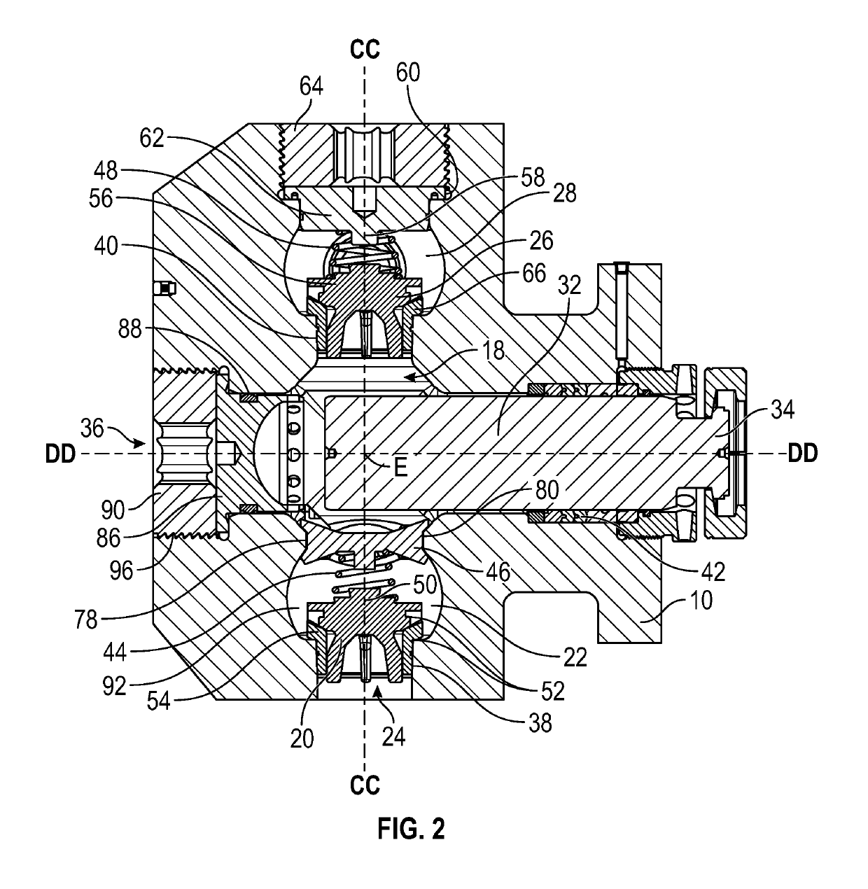
[0043]FIG. 2 is an exemplary side cross-sectional view of a representative bor...


PUM


Abstract

A reciprocating plunger pump fluid end having increased material thicknesses in typical high stress concentration areas includes locating valves in spherically segmented shaped suction and discharge bores adjacent to chamfered transition areas to provide for reduced stress concentrations, resistance to fatigue failure and erosion and ease of access for maintenance. Among other features the housing includes a valve retainer assembly integrally mounted inside the housing which includes a profile to reduce stresses in the bores and facilitate access for replacement of internal components.

Description

FIELD OF INVENTION[0001]The disclosure relates generally to a fluid end housing for reciprocating plunger pumps used, for example, in oil field operations. More particularly, the invention relates to the design and certain internal components of a fluid end housing to reduce stress and fatigue failure, and to increase erosion resistance, durability, and to permit ease of access for maintenance. These novel design features include, among other things, improved bore geometries, an improved valve spring retainer or keeper, and improved access lock nut.BACKGROUND[0002]High-pressure pumps are used for a variety of oilfield and mining applications such as in hydraulic fracturing for oil and gas wells. Hydraulic fracturing or “fracing” involves pumping fracturing fluids (i.e. a combination of water, cement, mud, frac sand and other materials) at high pressure into the wellbores to cause a potentially producing formation to fracture. These types of pumps include a power end and a fluid end ...

Claims


Application Information

Patent Timeline
Patent Type & Authority Applications(United States)
IPC IPC(8): F04B53/10F04B7/00F04B53/22F16K17/04
CPCF04B53/1032F16K17/048F04B7/0023F04B53/1087F04B53/22F04B53/007F04B53/1025F16K15/026
Inventor BROOKS, BRADLEY ALLANCONATSER, MICHAEL DAVIDCORNETT, SEAN CHRISTOPHERMCKELROY, RONDAII BAILEYMULLINS, BLAKESEYMOUR, STEPHEN
Owner ADVANCED UPSTREAM SOLUTIONS LLC
Why Eureka
Try Eureka