
Center pivot irrigation gooseneck with varying cross-sectional diameters

Active Publication Date: 2019-05-23
NELSON IRRIGATION
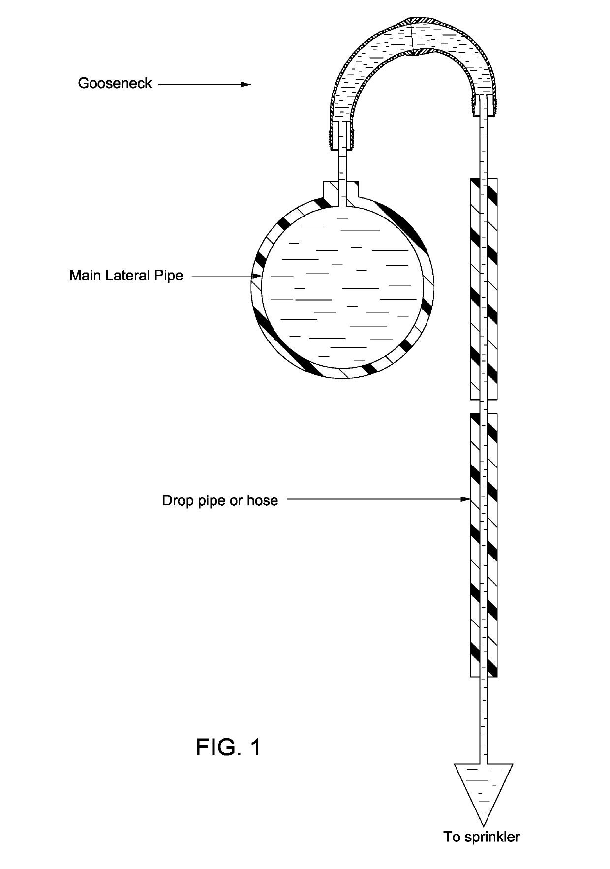
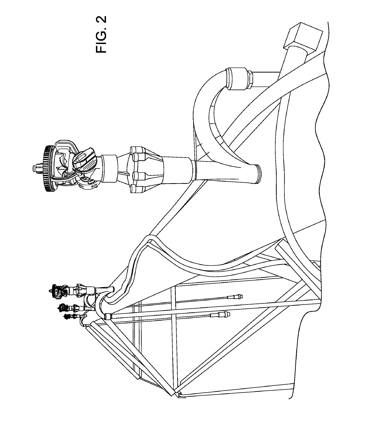
View PDF0 Cites 2 Cited by
  • Summary
  • Abstract
  • Description
  • Claims
  • Application Information

AI Technical Summary

Benefits of technology

The described gooseneck pipe design includes a two-piece mold design that optimizes flow paths to reduce pressure losses and mitigate the impact of secondary flow patterns. The cross-sectional diameter of the pipe is increased where fluid is turned, which helps to increase flow rates and decrease pressure losses. This design features a gradual increase in cross-sectional flow paths that slow down the average fluid velocity and reduce secondary flows. This design also includes a lofted flow path with two differently-radiused centerline / guide curves further reducing pressure losses. Test data supports these design features.

Problems solved by technology

Because of their relatively large irrigated area, pivot systems also require relatively large water volumes for proper operation.
The friction losses of these components have a large impact on the pumping requirements and operating costs of the irrigation system.
This redirection of the water has a high potential for increased friction losses.
As a consequence, geometries of existing gooseneck pipes are limited.

Method used


Image

  • Center pivot irrigation gooseneck with varying cross-sectional diameters
  • Center pivot irrigation gooseneck with varying cross-sectional diameters
  • Center pivot irrigation gooseneck with varying cross-sectional diameters

Examples


Embodiment Construction

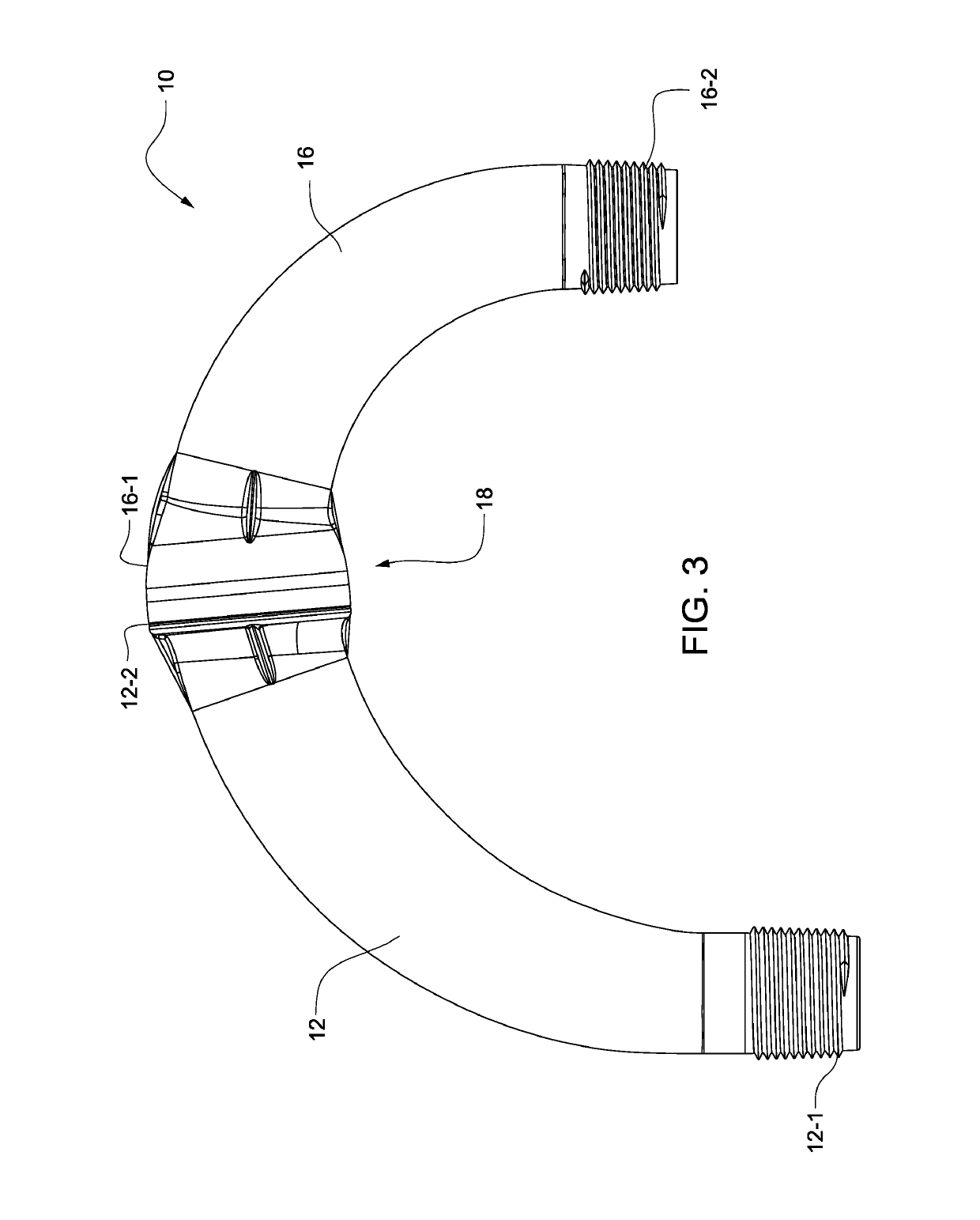
[0029]FIGS. 3-7 show a gooseneck pipe of a first exemplary embodiment. The gooseneck pipe 10 includes a first pipe half 12 having a first radiused centerline curve 14 (FIG. 4). A second pipe half 16 is fixed to the first pipe half via a spin weld or friction weld joint 18 or the like. References to the first pipe “half” and the second pipe “half” are not meant to be limited to equal halves of the gooseneck pipe, but rather are intended merely to reference separate portions of the gooseneck pipe. The second pipe half 16 includes a second radiused centerline curve 20 that is different from the first radiused centerline curve 14. As shown, the first radiused centerline curve 14 is tangent to the second radiused centerline curve 20. The first pipe half 12 may be an inlet pipe half, and the second pipe half 16 may be an outlet pipe half. The first radiused centerline curve 14 may be larger than the second radiused centerline curve 20. The first 12 and second 16 pipe halves define a flow ...


PUM

PropertyMeasurementUnit
Pressureaaaaaaaaaa
Angleaaaaaaaaaa
Flow rateaaaaaaaaaa

Abstract

A gooseneck pipe includes a first pipe half having a first radiused centerline curve, and a second pipe half fixed to the first pipe half and having a second radiused centerline curve. The first and second pipe halves define a flow path. Cross-sectional diameters of the first and second pipe halves vary along the flow path. The varying diameters of the first and second pipe halves serve to mitigate pressure losses due in part to Dean vortices or secondary flow patterns in the flow path when a fluid is turned in the gooseneck pipe.

Description

CROSS-REFERENCES TO RELATED APPLICATIONS[0001]This application claims the benefit of U.S. Provisional Patent Application Ser. No. 62 / 359,489, filed Jul. 7, 2016, the entire content of which is herein incorporated by reference.STATEMENT REGARDING FEDERALLY SPONSORED RESEARCH OR DEVELOPMENT[0002](NOT APPLICABLE)BACKGROUND[0003]The invention relates to a gooseneck pipe for use with center pivot irrigation and, more particularly, to a gooseneck pipe having an optimized flow path to mitigate pressure loss due in part to secondary flow patterns such as Dean vortices.[0004]Pivot systems consist of elevated lateral pipes that convey water from the inlet of the system, generally in the center of the irrigated area, to the outer boundary of the field. The lateral pipes are mechanically moved during irrigation to provide large irrigated areas relative to the number and size of the system components. Because of their relatively large irrigated area, pivot systems also require relatively large w...

Claims


Application Information

Patent Timeline
IPC IPC(8): F16L43/00F16L41/02F16L13/02F16L9/128
CPCF16L43/008F16L41/023F16L13/02F16L9/128A01G25/092F16L3/00A01G25/023A01G25/026B05B1/34F16L25/14F16L11/121
Inventor NELSON, CRAIG B.NELSON, REID A.GREENWOOD, RILEY D.LEINWEBER, CHAD D.TOWNSEND, MICHAEL R.
Owner NELSON IRRIGATION
Learn More