Side vertical mirror group and installation method thereof

a vertical mirror and side mirror technology, applied in the field of vertical mirror assembly, can solve the problems of increasing market requirements for imaging quality, increasing complexity of optical systems and the number of optical components therein, and complex process for processing and manufacturing of high-precision optical lenses, so as to reduce the axial displacement of the optical lens, ensure stability, and facilitate adjustment

Inactive Publication Date: 2019-05-23
SHANGHAI MICRO ELECTRONICS EQUIP (GRP) CO LTD
View PDF5 Cites 2 Cited by
  • Summary
  • Abstract
  • Description
  • Claims
  • Application Information

AI Technical Summary

Benefits of technology

[0029]In the above method of the present invention, the tightening screw exerts a force to limit radial displacement of the optical lens, and the supporting force provided by the elastic support to the optical lens can be easily adjusted by changing the degree of compression of the elastic support. In addition, the optical lens is fixed to the lens frame by

Problems solved by technology

Processing and manufacturing of high-precision optical lens is a very complex process.
Nowadays, complexity of optical systems and the numbers of optical components therein are increasing with market requirements on their imaging quality becoming more and more demanding.
The fixation methods need to consider the gravitational effects, so that the methods applicable for horizontally-oriented fixation is no longer applicable to the vertically-oriented fixation.
In this method, when load

Method used


Image

  • Side vertical mirror group and installation method thereof
  • Side vertical mirror group and installation method thereof
  • Side vertical mirror group and installation method thereof

Examples


embodiment 1

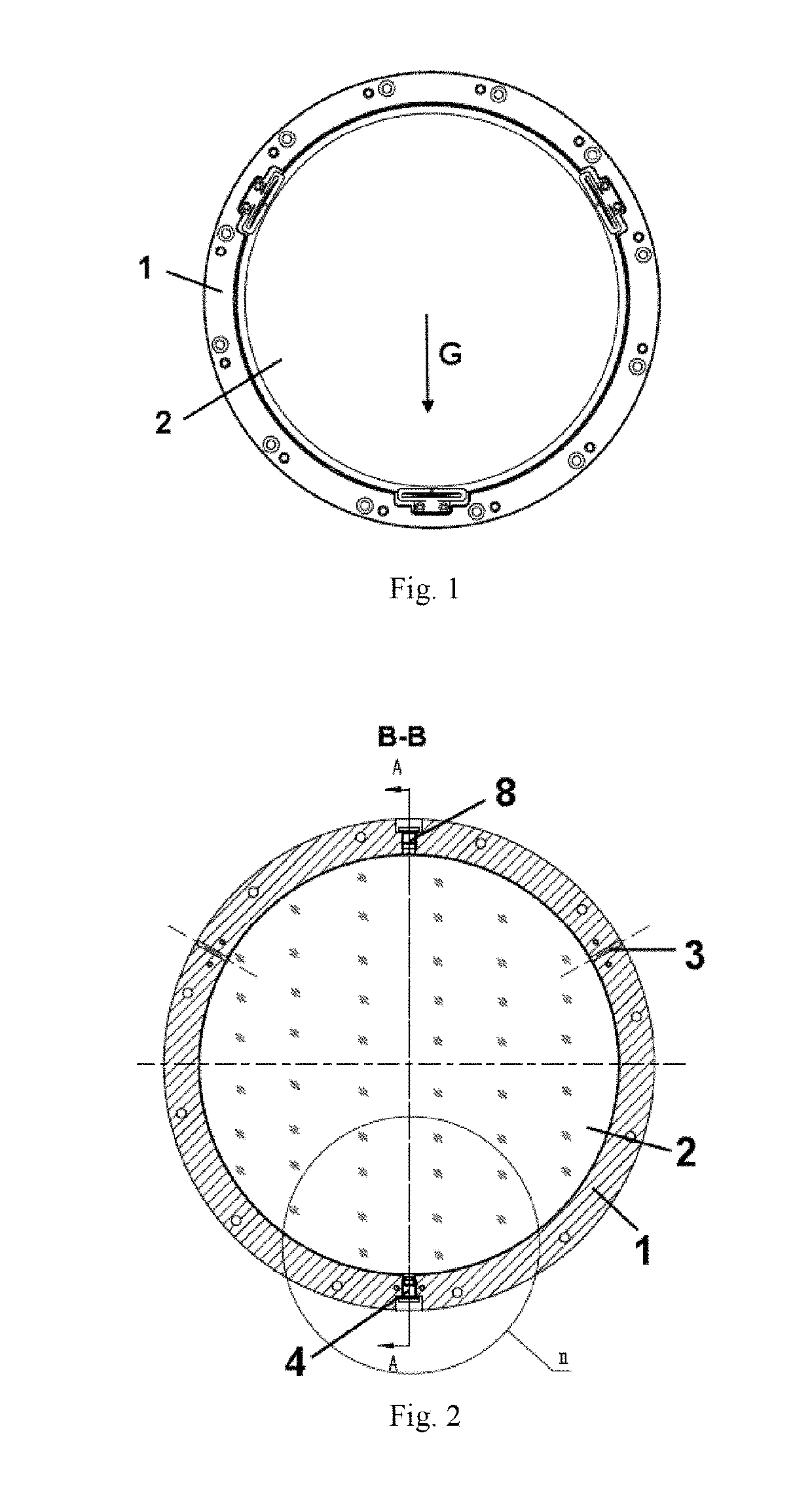
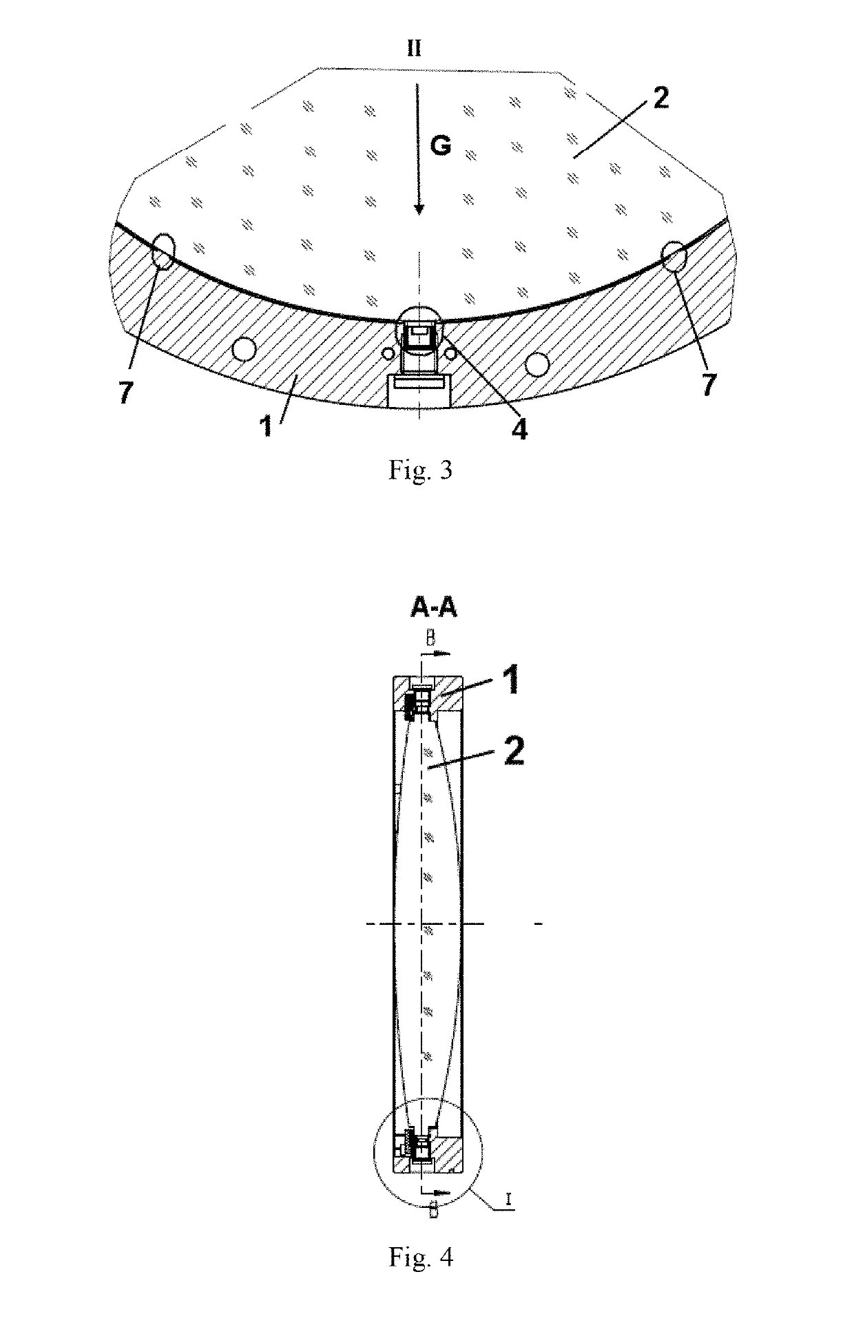
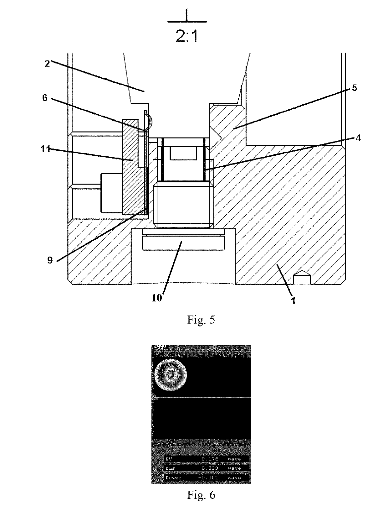
[0040]Referring now to FIGS. 1 to 5, a vertically-oriented lens assembly according to this embodiment includes: a lens frame 1 which is oriented vertically; an optical lens 2 surrounded and retained vertically by the lens frame 1; two rigid supports 7 that are symmetric to each other with respect to a vertical central axis of the lens frame 1, both integral with the lens frame 1, wherein the rigid supports 7 are both under a horizontal central axis of the lens frame 1 and the rigid supports 7 are both in direct contact with the optical lens 2; an elastic support 4 right under the optical lens 2, the elastic support 4 is able to be brought into contact with the optical lens 2 through adjustment of an adjusting screw 10 penetrating through the lens frame 1 from right under a bottom of the lens frame; and a tightening screw 8 is disposed right at a top of the lens frame 1 for limiting radial displacement of the optical lens 2.

[0041]In the vertically-oriented lens assembly according to ...

embodiment 2

[0046]In this embodiment, there is provided a method for making the vertically-oriented lens assembly of Embodiment 1. The method includes the steps of:

[0047]S1) vertically orienting the lens frame 1;

[0048]S2) vertically disposing the optical lens 2 on the rigid supporting member 5 of the lens frame 1;

[0049]S3) applying a force to the optical lens 2 via the tightening screw 8, the force is equal in magnitude to the gravity G of the optical lens 2, making each of the rigid supports 7 abut the optical lens 2 to limit radial displacement of the optical lens;

[0050]S4) adjusting, with aid of a force gauge, a supporting force provided by the elastic support 4, such that the elastic support supports the optical lens 2 with a supporting force equal in magnitude to ⅓ the gravity G of the optical lens 2, and then locking an adjusting screw 10;

[0051]S5) attaching one or more pre-tensioning spring leaves 6 based on the practical need, measuring a tension force produced by the pre-tensioning spr...


PUM


Abstract

A vertically-oriented lens assembly is disclosed which includes: a lens frame (1); an optical lens (2); two rigid supports (7) that are symmetric to each other with respect to a vertical central axis of the lens frame (1), both integral with the lens frame (1), and both in direct contact with the optical lens (2); an elastic support (4) disposed right under the optical lens (2) and brought into contact with the optical lens (2) by an adjusting screw (10); and a tightening screw (8) disposed on the top of the lens frame (1) for limiting radial displacement of the optical lens (2). A method for forming the vertically-oriented lens assembly is also disclosed, including: disposing the optical lens (2) on a rigid supporting member (5) of the lens frame (1) so that the optical lens (2) is vertically oriented; applying a force to the optical lens (2) via the tightening screw (8) to make the rigid supports (7) both abut the optical lens (2); adjusting a supporting force provided by the elastic support (4) to the optical lens (2) by the adjusting screw (10); attaching pre-tensioning spring leaf (6) and dispensing an adhesive through bores (3) to fixedly attach the optical lens (2) to the lens frame (1); and attaching an axial stop block (11), allowing high stability and a high surface precision and it can be used in engineering applications.

Description

TECHNICAL FIELD[0001]The present invention relates to a lens assembly and, in particular, to a vertically-oriented lens assembly and a method of installing the lens assembly.BACKGROUND[0002]Processing and manufacturing of high-precision optical lens is a very complex process. Nowadays, complexity of optical systems and the numbers of optical components therein are increasing with market requirements on their imaging quality becoming more and more demanding. Currently, such optical components are required to be positioned with a precision on the order of microns and to maintain a surface precision of tens of nanometers.[0003]A catadioptric system typically has both vertical and horizontal optical axes. That is, there are both horizontally and vertically oriented optical components in the system, which are subject to rather different gravitational effects. For an optical component with a large diameter (usually >200 mm), gravitational effects cannot be ignored. The fixation methods...

Claims


Application Information

Patent Timeline
IPC IPC(8): G02B7/02
CPCG02B7/026G02B7/025G02B7/022G02B7/023G02B7/028
Inventor WANG, MINGTIANLIU, GUOGAN
Owner SHANGHAI MICRO ELECTRONICS EQUIP (GRP) CO LTD
Why Eureka
Try Eureka