
Eureka
For R&D, Eureka makes reading and utilizing patents & technical documents easy.
Eureka AIR
Designed for self-driven R&D workflows. Generate viable solutions, solve complex R&D challenges, empower your innovation with AI.

Eureka Materials
Designed for material experts only. Revolutionize your material R&D, from search, analyze, to developing new materials.

TechResearch
Generate reliable direction feasibility study reports for your R&D in just a few steps.

TechSeek
Discover and master advanced knowledge NOW. Basics, ideas, possibilities, all at once.

TechMind
As an expert in R&D Theories, TechMind can generates customized viable solutions instantly.

TechRisk
Analyze your overall solution with one click, know your potential R&D risks in advance.

TechMonitor
Get weekly tech updates, stay abreast of the latest tech innovations and key insights.
Noise monitoring device
- Summary
- Abstract
- Description
- Claims
- Application Information
AI Technical Summary
Benefits of technology
Problems solved by technology
Method used
Image

Examples
example 1
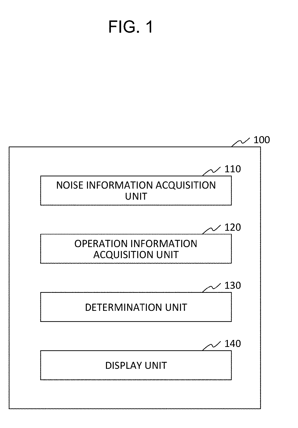
[0032]The operation of the noise monitoring device 100 in the case where the operation information of all the machines is displayed in case of noise generation will be described with reference to FIG. 5.
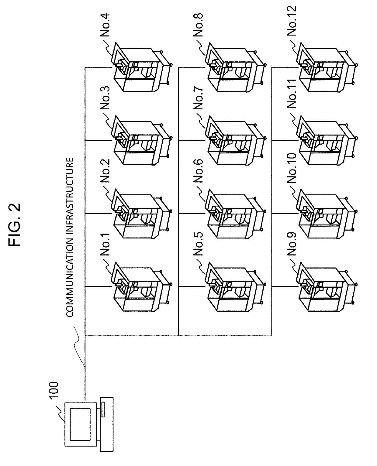
[0033]The noise monitoring device 100 is connected with 12 machines No. 1 to No. 12. Let us assume that generation of noise exceeding a predetermined threshold is detected in the machine No. 11 at time 9:44:15. The noise information acquisition unit 110 receives notification of the noise generation from the machine No. 11 and generates and saves the noise information.
[0034]The operation information acquisition unit 120 continually periodically collects and accumulates the operation information from all the machines in the factory. When new noise information is saved in the noise monitoring device 100, the determination unit 130 extracts those of pieces of operation information collected at a point in time near the time of noise generation out of the accumulated pieces of operation in...
example 2
[0036]The operation of the noise monitoring device 100 in the case where the operation information of all the machines is displayed when an alarm suspected to be caused by noise is generated in the machines will be described with reference to FIG. 6. In Example 1, the operation information of all the machines is displayed in case of actual noise generation. In Example 2, on the other hand, the same processing as in the case of noise generation is performed if the alarm liable to be generated by noise is generated in the machines although the noise generation is not detected by the noise information acquisition unit 110.
[0037]The noise monitoring device 100 is connected with 12 machines No. 1 to No. 12. Let us assume that an alarm is generated in the machine No. 11 at time 9:44:15. The noise information acquisition unit 110 receives notification of the alarm generation from the machine No. 11 and saves alarm information. The alarm information includes, for example, identification inf...
example 3
[0040]The operation of the noise monitoring device 100 in the case where only the operation information of those machines with a high probability of being a cause of noise generation is displayed in case of noise generation will be described with reference to FIG. 7.
[0041]The noise monitoring device 100 is connected with 12 machines No. 1 to No. 12. Let us assume that generation of noise exceeding a predetermined threshold is detected in the machine No. 11 at time 9:44:15. The noise information acquisition unit 110 receives notification of the noise generation from the machine No. 11 and generates and saves the noise information.
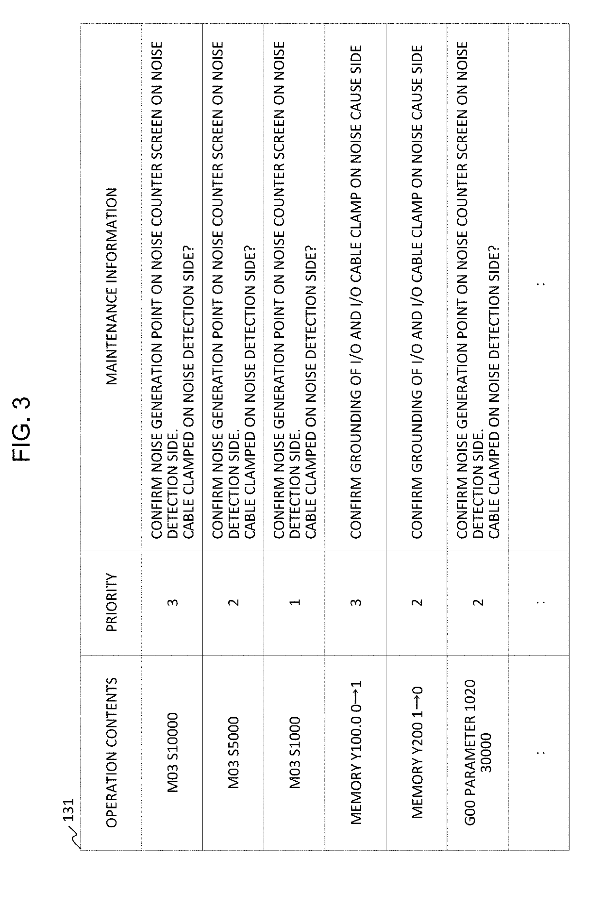
[0042]The operation information acquisition unit 120 continually periodically collects and accumulates the operation information from all the machines in the factory. Moreover, the determination unit 130 is assumed to have saved the data base 131 shown in FIG. 3 in advance. It is assumed that higher priorities have greater numbers in the data base 131 and th...
PUM
 Abstract
Description
Claims
Application Information
 - R&D Engineer
- R&D Manager
- IP Professional
- Industry Leading Data Capabilities
- Powerful AI technology
- Patent DNA Extraction
Browse by: Latest US Patents, China's latest patents, Technical Efficacy Thesaurus, Application Domain, Technology Topic, Popular Technical Reports.
© 2024 PatSnap. All rights reserved.Legal|Privacy policy|Modern Slavery Act Transparency Statement|Sitemap|About US| Contact US: help@patsnap.com