Check patentability & draft patents in minutes with Patsnap Eureka AI!

Display control device and display control system

a control device and control system technology, applied in the field of display control devices and display control systems, can solve the problems of difficult operation, inability to produce images, and inability to achieve similar quality of obtained images, so as to facilitate the manipulation of zoom magnification by operators

Active Publication Date: 2019-05-23
JVC KENWOOD CORP A CORP OF JAPAN
View PDF4 Cites 1 Cited by
  • Summary
  • Abstract
  • Description
  • Claims
  • Application Information

AI Technical Summary

Benefits of technology

The present application aims to provide a display control device and system that can easily adjust custom magnification for various cameras and ensure consistent image quality. This technology aims to improve the user's experience when interacting with the cameras.

Problems solved by technology

In such a case, when setting the magnification of two cameras, it is difficult to produce an image where the magnification of the image has been changed according to an operator's will, because there is a difference in an operator's feeling against changing magnification between respective operation elements.
Furthermore, if the number of cameras gets increased, an operator's feeling is further complicated to cause the operation to be difficult.
Meanwhile, a camera itself has a problem of luminance unevenness (i.e. shading) caused by peripheral darkening of an optical system or inequality of sensitivity of an image pickup element and therefore, it is necessary to perform a shading correction to remove such shading.
However, as the degrees of shading correction are different for the respective models of cameras, there arises a problem that obtained images are not made to be similar in quality.
However, Patent Literature 1 does not describe a technique of adjusting the quality of images of different types of cameras.
As mentioned above, in the conventional display control device of Patent Literature 1, when controlling displaying of images taken by a plurality of cameras and if there is a difference in the model of the cameras, it is difficult for an operator to manipulate the zoom magnifications of the cameras.
Additionally, if the model of cameras differs, it is difficult to uniformize image quality of images taken by respective cameras and therefore, there arises a problem of giving discomfort to a viewer, in a situation of displaying the images taken by the plurality of cameras on a single screen separately.

Method used


Image

  • Display control device and display control system
  • Display control device and display control system
  • Display control device and display control system

Examples


Embodiment Construction

[0019]An embodiment will be described with reference to the drawings.

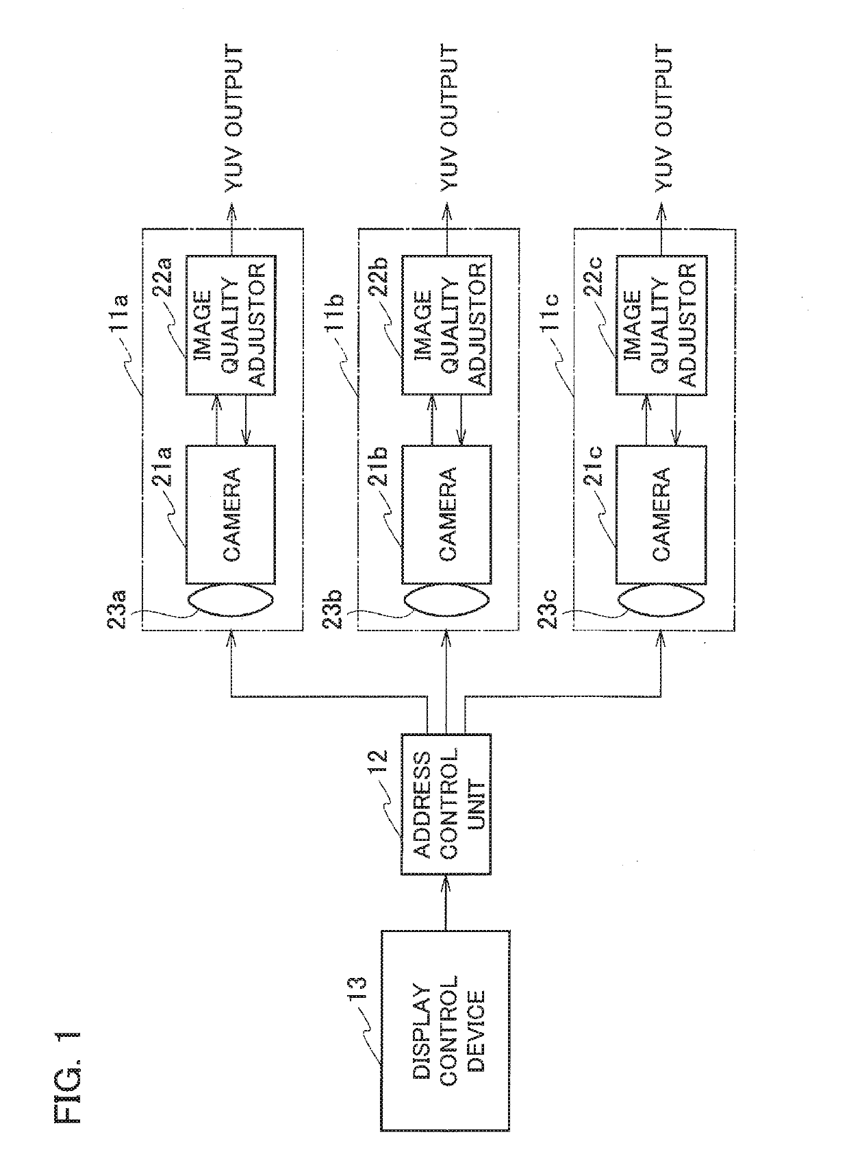
[0020]As illustrated in FIG. 1, a display control system according to the embodiment includes a plurality of (three in FIG. 1) imaging devices 11a, 11b, 11c, an address control unit 12 connected to the respective imaging devices 11a, 11b, 11c, and a display control device 13. In the following description, if indicating each imaging device in distinction from others, the device will be represented with a suffix such as “11a”, “11b” or “11c”, and if the imaging device is indicated with no distinction, it will be represented with no suffix but “11” representatively. The same applies to other codes.

[0021]The imaging device 11a includes a camera 21a, an image quality adjustor 22a, and a lens 23a. Each of the imaging devices 11b, 11c also has the similar configuration and includes a camera 21b, 21c, an image quality adjustor 22b, 22c, and a lens 23b, 23c.

[0022]The camera 21 acquires an image focused by the lens 23 and c...


PUM


Abstract

A display control device for controlling displaying of images taken by a plurality of cameras each having a function of changing a zoom magnification includes: an operation unit including an operation element provided for each of the cameras to accept an operator's operation of setting the zoom magnification of the cameras, the operation unit being configured to output a input pulse signal corresponding to an operation amount of the operation element; and a W / T pulse convertor configured to convert the input pulse signal to a reference pulse signal that is uniformized variations in the zoom magnification of respective cameras with respect to a predetermined operation amount of the operation element, and output the second control signal to a corresponding camera.

Description

CROSS REFERENCE TO RELATED APPLICATION[0001]The present application is based on, and claims priority from Japanese Patent Application No. 2017-221449; filed Nov. 17, 2017, the disclosure of which is hereby incorporated by reference herein in its entirety.BACKGROUNDTechnical Field[0002]The present application relates to a display control device and a display control system, both of which are provided for controlling displaying of images taken by a plurality of cameras each having a zooming function.Related Art[0003]In a studio or live place, for example, an attempt is often made to take and display a plurality of images simultaneously with a plurality of cameras each having functions of panning (i.e. rotating an orientation of lenses of a camera in a horizontal direction), tilting (i.e. rotating the orientation of lens of a camera in a vertical direction) and zooming (i.e. changing the magnification of a camera in a range from telephoto up to wide angle). Here, these cameras having s...

Claims


Application Information

Patent Timeline
Patent Type & Authority Applications(United States)
IPC IPC(8): H04N5/232G06F3/0484H04N23/76
CPCH04N5/23296G06F3/04847H04N5/23216H04N23/69H04N23/695H04N25/61H04N23/62
Inventor YUFUNE, SHUTA
Owner JVC KENWOOD CORP A CORP OF JAPAN
Features
  • R&D
  • Intellectual Property
  • Life Sciences
  • Materials
  • Tech Scout
  • Unparalleled Data Quality
  • Higher Quality Content
  • 60% Fewer Hallucinations
Learn More