
Method and device for operating a motor vehicle

a motor vehicle and vehicle control technology, applied in the direction of control devices, vehicle components, external condition output parameters, etc., can solve the problems of difficult compensation, high cost, and delayed stopping of the motor vehicle, and achieve safe and accurate operation, reduce the duration of a comfortable deceleration to a standstill, and improve the accuracy.

Active Publication Date: 2019-05-30
ROBERT BOSCH GMBH
View PDF0 Cites 0 Cited by
  • Summary
  • Abstract
  • Description
  • Claims
  • Application Information

AI Technical Summary

Benefits of technology

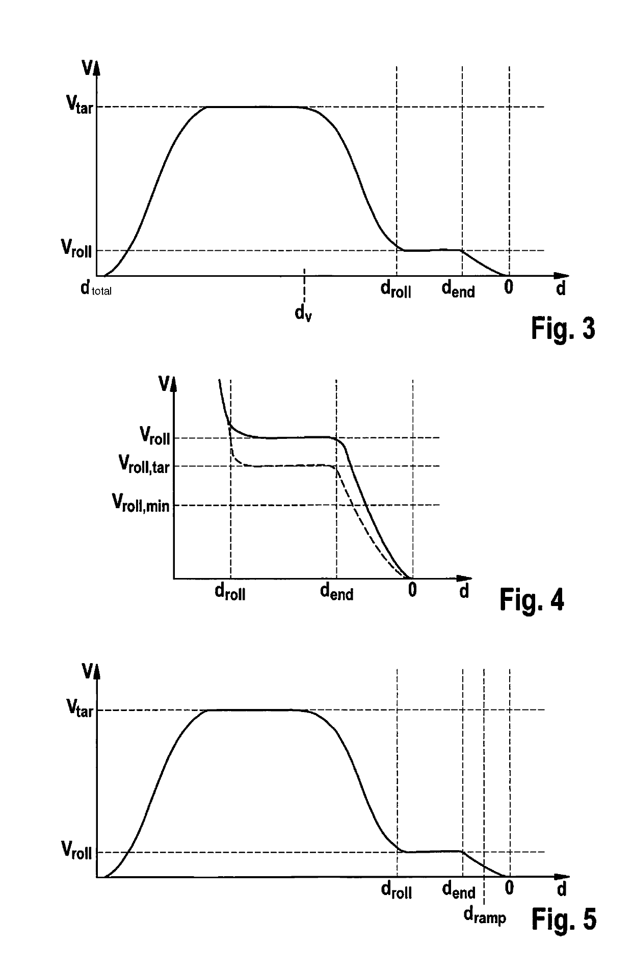
The present invention provides a method for safely and accurately reaching a target location in a motor vehicle. The method involves a rolling phase where the motor vehicle is decelerated and then stopped at a predefined distance from the target location. This rolling velocity is maintained until the vehicle reaches a second distance, where it is reduced to a predefined minimum. The method also includes a setpoint deceleration that is predefined between 0.1 m / s2 to 1 m / s2, which ensures a comfortable driving experience. The rolling velocity is set to the minimum of the driving velocity if it falls below the rolling velocity prior to step c. The method also optimizes driving comfort on short driving segments by constantly decelerating the motor vehicle up to the target location starting from a third distance, which is smaller than the second distance.

Problems solved by technology

Another challenge arises in that an unintentional, premature stopping of the motor vehicle may occur at very low velocities in the interaction between the drive unit and the braking system, if, for example, the motor vehicle must overcome an obstacle, for example a curb or the like, in order to reach the target location.
Due to inaccuracies or tolerances in the braking system, however, errors build up over time that are difficult to compensate for.
These reasons result in the stopping accuracy of the motor vehicle no longer being able to be improved past a certain point.

Method used


Image

  • Method and device for operating a motor vehicle
  • Method and device for operating a motor vehicle

Examples


Embodiment Construction

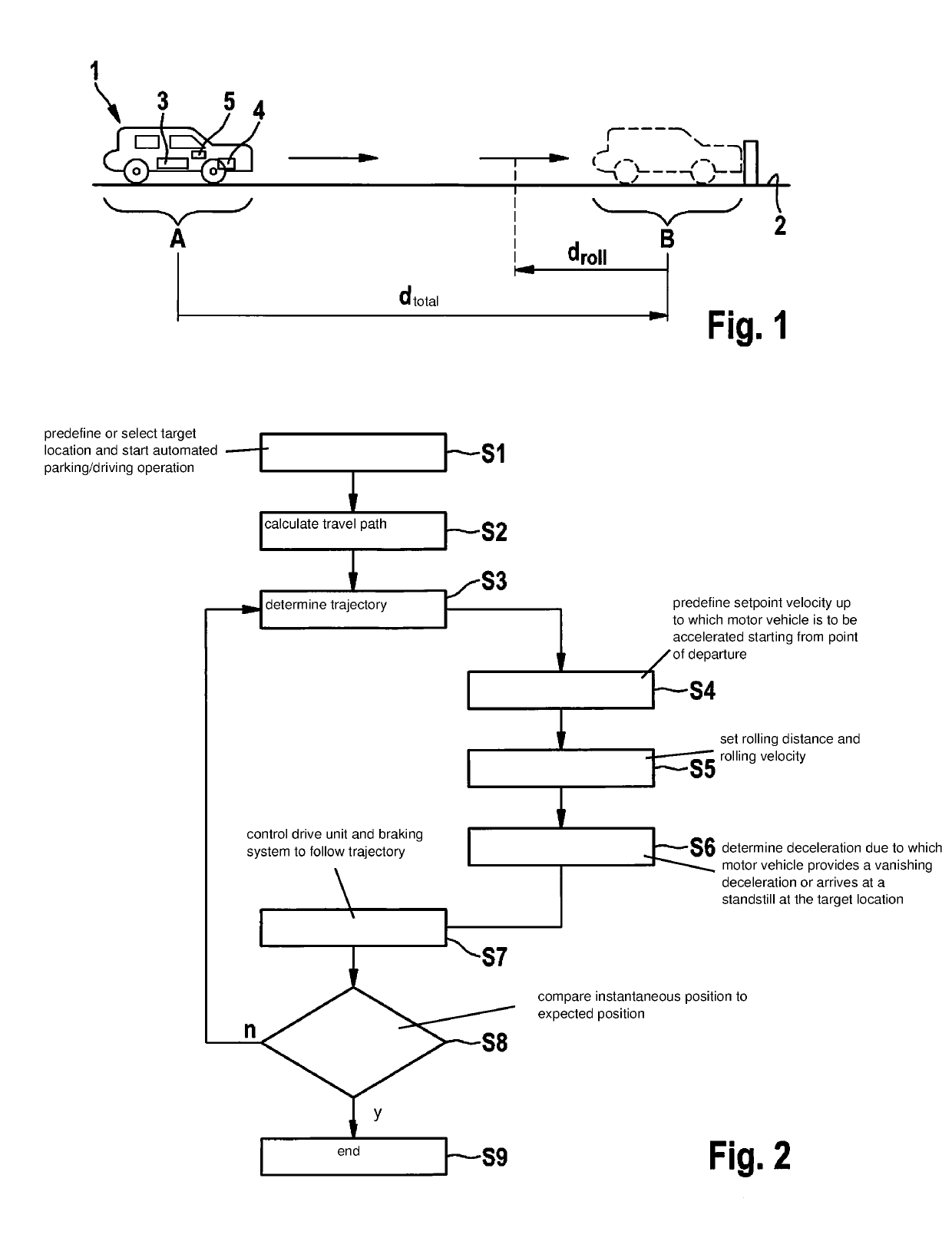
[0028]FIG. 1 shows a simplified representation of a motor vehicle 1, which is located on solid ground, for example, a parking lot 2, at a position A. Motor vehicle 1 has a drive unit 3, which includes, for example, an internal combustion engine and / or at least an electric machine, which is connected or connectable to the wheels of the motor vehicle directly or via a transmission. Furthermore, motor vehicle 1 includes a braking system 4, which may exert a brake force as needed on at least one wheel of motor vehicle 1 to decelerate motor vehicle 1. In particular, if drive unit 3 includes one or multiple electric machines, then these may also be used by braking system 4 for decelerating or braking motor vehicle 1. Otherwise, braking system 4 preferably includes one or multiple wheel brakes which interact mechanically, for example, through friction, with the wheels of the motor vehicle. Furthermore, motor vehicle 1 includes a control unit 5 which is designed to control drive unit 3 and ...


PUM


Abstract

A method for operating a motor vehicle, the motor vehicle being automatically accelerated and decelerated as a function of an instantaneous position and a predefinable target location, so that it comes to a standstill at the target location, including the following steps: a) accelerating the motor vehicle, in particular from a standstill, to a predefined setpoint velocity; b) up to a predefined first distance of the motor vehicle to the target location, decelerating the motor vehicle to a predefined rolling velocity; c) starting at a predefined second distance of the motor vehicle to the target location, decelerating the motor vehicle to a standstill, the second distance to the target location being smaller than the first distance.

Description

[0001]CROSS REFERENCE[0002]The present application claims the benefit under 35 U.S.C. § 119 of German Patent Application No. DE 102017221097.4 filed on Nov. 24, 2017, which is expressly incorporated herein by reference in its entirety.FIELD[0003]The present invention relates to a method for operating a motor vehicle, the motor vehicle being automatically accelerated and decelerated as a function of an instantaneous position and a predefinable target location so that it comes to a standstill at the target location.[0004]In addition, the present invention relates to a device for carrying out the method.BACKGROUND INFORMATION[0005]Present-day motor vehicles increasingly include driver assistance systems, which also facilitate automated driving functions to relieve the driver. These include, for example, parking assistants and pilots, which in addition to automated transverse guidance also automate the longitudinal guidance of the motor vehicle. To ensure a preferably comfortable longit...

Claims


Application Information

Patent Timeline
Patent Type & Authority Applications(United States)
IPC IPC(8): B60W30/06B60W10/04B60W10/18
CPCB60W30/06B60W10/04B60W10/18B60W2720/10B60W10/10B60W30/18018B60W30/16B60W30/18072B60W2754/10
Inventor TOLKSDORF, CHRISTIANCREPIN, BETTINASCHAEFFLER, RALFBRETTSCHNEIDER, THOMAS
Owner ROBERT BOSCH GMBH
Learn More