Oil Analysis

a technology for oil and oil suspension, applied in the field of oil analysis, can solve the problems of oil becoming contaminated by particulates, unnecessary expenses, and high cost and time consumption, and achieve the effects of reducing the risk of contamination, and reducing the quality of oil

Active Publication Date: 2019-05-30
CASTROL LTD
View PDF4 Cites 6 Cited by
  • Summary
  • Abstract
  • Description
  • Claims
  • Application Information

AI Technical Summary

Benefits of technology

[0015]Accordingly, the present invention provides an economical method for the on-site assessment of the condition of an industrial oil. This enable

Problems solved by technology

Nevertheless, over time, these oils may become contaminated by particulates.
However, since these methods involve off-site measurement of samples, they are expensive and time consuming, e.g. due to the cost and time involved with shipping oil samples or filter patches to the specialist laboratory.
In some cases, unnecessary expenses may be incurred by sending oil samples for analysis more often than is required (around 90% of samples sent to laboratories are considered ‘clean’, i.e. not to contain unusual quantities or types of wear particle).
Moreover, the time taken to obtain the W

Method used


Image

  • Oil Analysis
  • Oil Analysis

Examples


example 1

g Wear Particles from an Oil Sample

[0080]A filter paper holder comprising a funnel and a cover was washed with white spirit. A filter paper, 13 mm in diameter and having a pore size of 3 μm, was inserted into the wet cover using tweezers, and the funnel then screwed into the cap.

[0081]A 10 ml sample of used gear oil and 10 ml of white spirit was extracted into a syringe via rubber tubing. The rubber tubing was attached to an inlet in the cover of the filter paper holder. An outlet in the funnel of the filter paper holder was attached to the inlet of a waste container. The syringe was used to push the diluted oil sample through the filter paper.

[0082]The filter paper was washed with a further 10 ml of white spirit, extracted and delivered using the syringe and optionally rubber tubing.

[0083]The filter paper was removed from the filter paper holder and placed on a sample holder. The filter paper was left to air dry for about 10 minutes.

example 2

an Optical Image of the Separated Wear Particles

[0084]A Celestron® Digital Microscope Pro was attached to a mobile phone via a USB device. The microscope was positioned over the filter paper and instructions were sent from the mobile phone to the camera to capture an image and transmit the image back to the mobile phone. The separated wear particles were illuminated by a distributed light source when the image was captured.

example 3

the Image of the Oil, and Generating Information about the Condition of the Oil

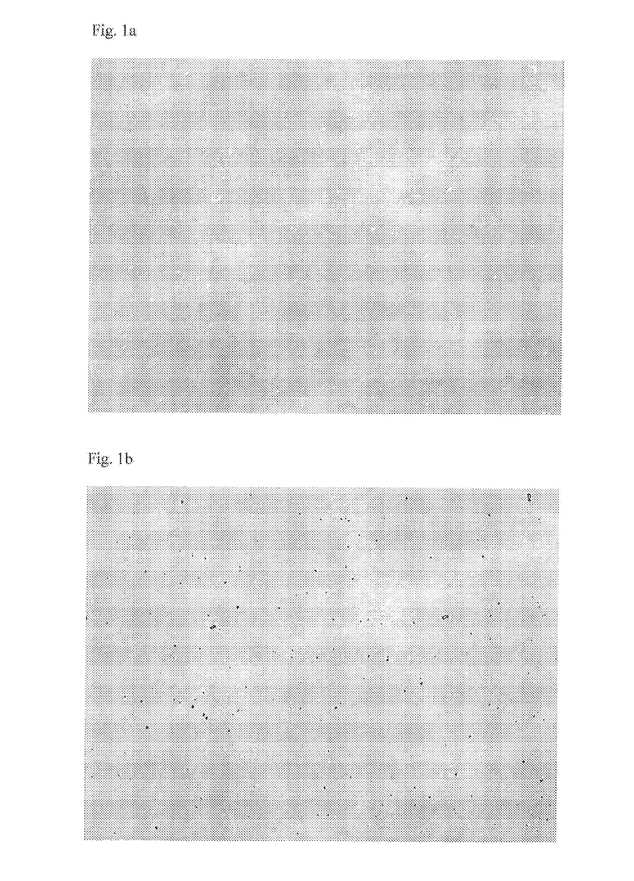
[0085]The image was analysed using the mobile phone by a process in which the separated wear particles were identified and marked in the image. FIG. 1a shows the image taken by the camera; and FIG. 1b shows the image after wear particles have been identified and marked using the software application run on the processor of the mobile phone. Features including the size and number of the identified wear particles were determined.

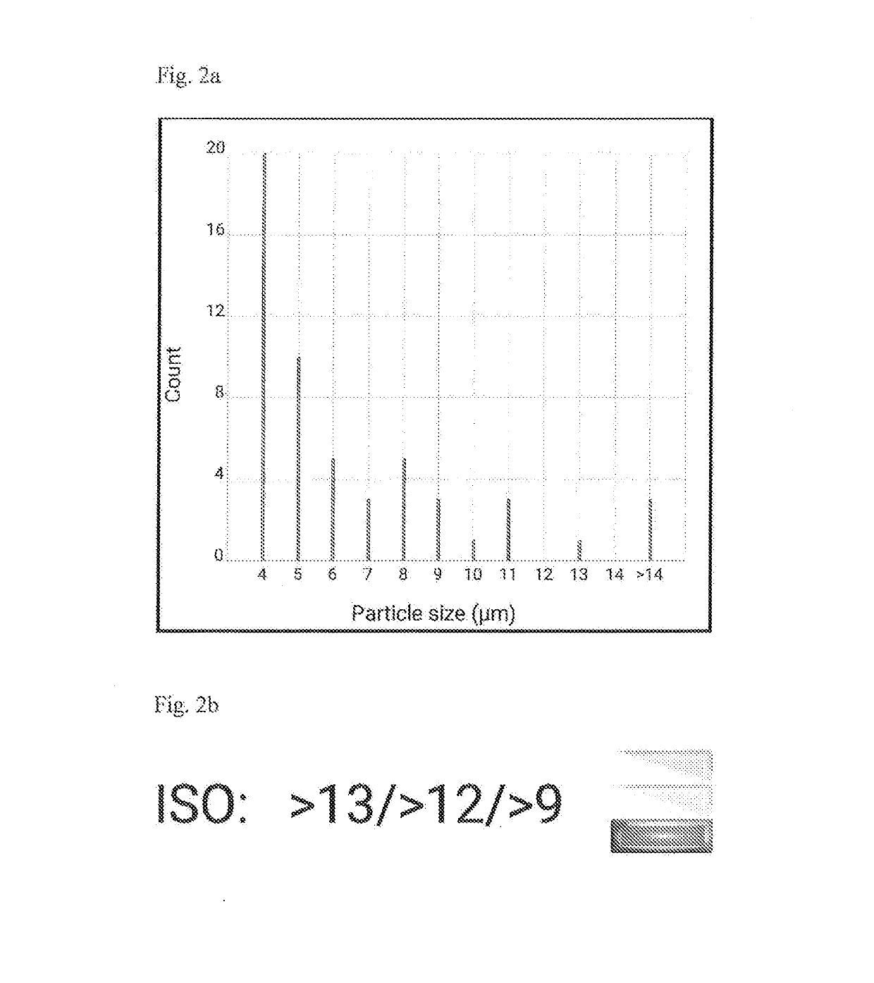
[0086]Information on the cleanliness of the oil was output through a display on the mobile phone. FIG. 2a shows a graph of the number of particles of different sizes contained within the oil sample that was output through a display on the mobile phone. FIG. 2b shows the ISO classification that the oil sample was calculated to have from the image, and that was also output through a display on the mobile phone. A traffic light coding system, shown to the right of FIG. 2b, was further ...


PUM


Abstract

A method for assessing the condition of an oil using a portable computer coupled to a camera comprises: separating wear particles from a sample of the oil; capturing an image of the separated wear particles using the camera; and analysing the image and generating information about the condition of the oil using the portable computer. The method may be used for tracking the condition of an oil in a machine over a period of time. The methods are particularly useful for assessing the condition of an industrial oil e.g. a lubricating oil that has been used to lubricate moving parts in a machine.

Description

CROSS-REFERENCE TO RELATED APPLICATIONS[0001]This application claims priority to U.S. Provisional Patent Application No. 62 / 337,840, filed May 17, 2016, which is hereby incorporated herein by reference in its entirety.FIELD OF THE INVENTION[0002]The present invention relates to a method for assessing the condition of an oil. In particular, the present invention relates to a method in which information obtained from the on-site analysis of wear particles contained within an oil may be used as an indication of the condition of the oil.BACKGROUND OF THE INVENTION[0003]Oils such as lubricants, hydraulic fluids, compressor oils, turbine oils, metal working fluids, bunker fuels and greases are typically employed with any moving parts in a machine. Nevertheless, over time, these oils may become contaminated by particulates. Particulates include wear particles which are generated due to the friction created as parts in a machine move against one another or originate from ingress of foreign ...

Claims


Application Information

Patent Timeline
IPC IPC(8): G01N33/28G01N15/02G01N15/06
CPCG01N33/2888G01N15/0227G01N15/0643G01N2015/0053G01N2015/0687G01N2015/0693G01N2015/1486
Inventor GAEMERS, SANDERRABENAU, BRYANJERUSALEM, MARCEL
Owner CASTROL LTD
Why Eureka
Try Eureka