Supercharge Your Innovation With Domain-Expert AI Agents!

Touch panel control apparatus, touch panel control method, and input display apparatus

a control apparatus and touch panel technology, applied in the direction of instruments, computing, electric digital data processing, etc., can solve the problems of gate driven noise, touch panel may malfunction, and position signal noise from the touch panel

Active Publication Date: 2019-05-30
SHARP KK
View PDF2 Cites 0 Cited by
  • Summary
  • Abstract
  • Description
  • Claims
  • Application Information

AI Technical Summary

Benefits of technology

The patent aims to develop a technology that can prevent the influence of gate drive noise in an input display apparatus that supports multiple types of video signals. The technical effect of this innovation is to improve the accuracy and reliability of the input display apparatus.

Problems solved by technology

Here, noise may occur in the position signal from the touch panel due to driving of the gate of the liquid crystal display apparatus (the gate of a thin film transistor (TFT) serving as a switching element (active element) disposed in each pixel).
This gate driven noise is likely to occur as the sensor surface of the touch panel is increased in size, that is, as the screen of the liquid crystal display apparatus is increased in size.
In other words, the touch panel may malfunction.
The gate driven noise notably occurs as the distance between the touch panel and the screen of the liquid crystal display apparatus is decreased, particularly in a structure in which the touch panel is provided on the screen of the liquid crystal display apparatus through known direct bonding.
Accordingly, there is a disadvantage in that, for example, the influence of the gate driven noise is avoided when the video signal of a certain kind is input but the influence of the gate driven noise is not avoided when the video signal of another kind is input.
In other words, it is not possible to reliably avoid the influence of the gate driven noise in the touch panel display supporting input of the video signals of multiple kinds with the technology disclosed in Japanese Unexamined Patent Application Publication No. 9-128146.
The amount of delay is set in advance so that a period when noise appearing in the position signal due to driving of a gate of the display apparatus, that is, gate driven noise occurs is within the disabled period.

Method used


Image

  • Touch panel control apparatus, touch panel control method, and input display apparatus
  • Touch panel control apparatus, touch panel control method, and input display apparatus
  • Touch panel control apparatus, touch panel control method, and input display apparatus

Examples


first embodiment

[0026]The present disclosure is applied to, for example, a touch panel display. A touch panel display in the related art will now be described before the touch panel display to which the present disclosure is applied is described.

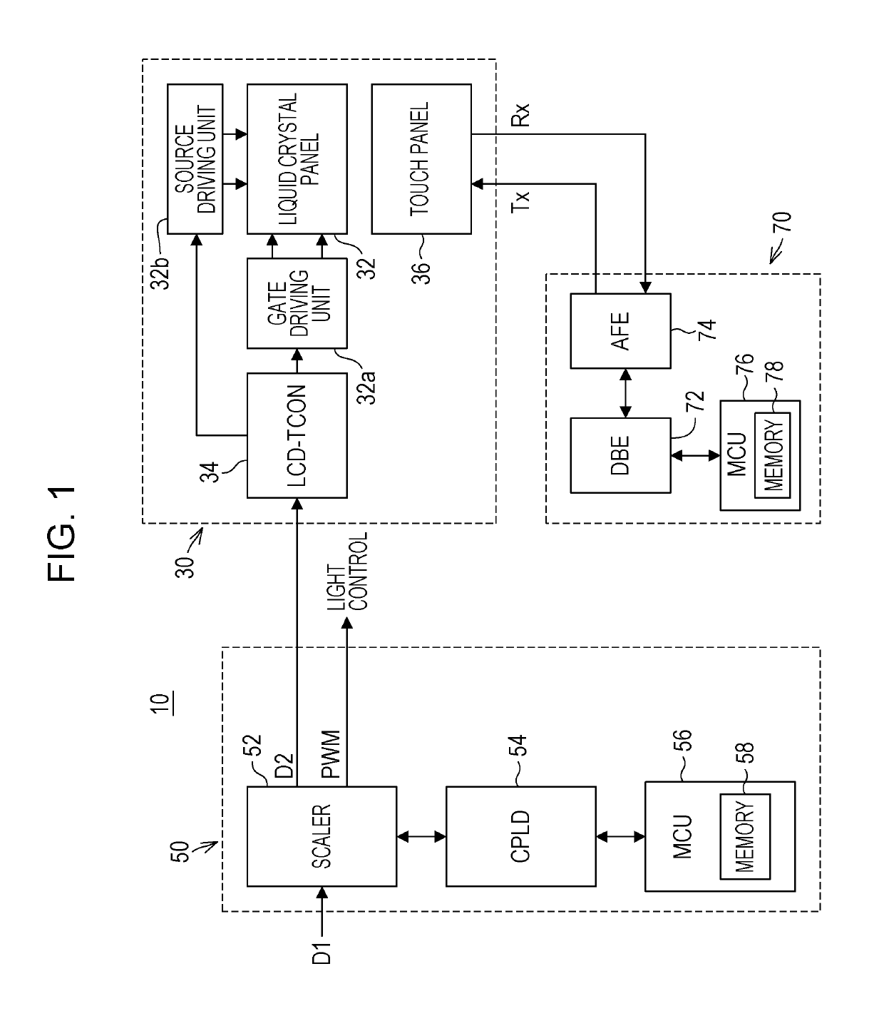
[0027]FIG. 1 is a block diagram schematically illustrating a configuration of an electrical portion of a touch panel display 10 in the related art. Referring to FIG. 1, the touch panel display 10 includes a liquid crystal module 30, a main interface board 50, and a touch panel control board 70.

[0028]The liquid crystal module 30 includes an active matrix drive liquid crystal panel 32, a gate driving unit 32a, a source driving unit 32b, a liquid crystal display-timing controller (LCD-TCON) 34, and a touch panel 36.

[0029]The liquid crystal panel 32 is composed of, for example, a polarizing filter, a glass substrate, a liquid crystal layer, and a backlight although a detailed description of them is omitted herein. The liquid crystal panel 32 forms a screen (an ...

second embodiment

[0074]A second embodiment of the present disclosure will now be described.

[0075]A touch panel display 10b according to the second embodiment results from further modification of the touch panel display 10a according to the first embodiment. Specifically, as illustrated in FIG. 11, in the touch panel display 10b according to the second embodiment, a frequency multiplication circuit 62 is formed by the CPLD 54 and the pseudo horizontal synchronization signal pHS is supplied to the frequency multiplication circuit 62. The frequency multiplication circuit 62 multiplies the frequency of the input pseudo horizontal synchronization signal pHS by two. A multiplied synchronization signal mHS subjected to the multiplication by the frequency multiplication circuit 62 is supplied to the delay circuit 60. The remaining components in the touch panel display 10b according to the second embodiment are the same as those in the touch panel display 10a according to the first embodiment.

[0076]The frequ...

third embodiment

[0083]A third embodiment of the present disclosure will now be described.

[0084]A touch panel display 10c according to the third embodiment results from further modification of the touch panel display 10b according to the second embodiment. Specifically, as illustrated in FIG. 15, in the touch panel display 10c according to the third embodiment, a pseudo vertical synchronization signal pVS is output from the scaler 52. The pseudo vertical synchronization signal pVS is synchronized with the vertical synchronization signal VS included in the converted video signal D2. In other words, the scaler 52 has a function to generate the pseudo vertical synchronization signal pVS and, strictly, the ASIC composing the scaler 52 is designed so as to provide the function to generate the pseudo vertical synchronization signal pVS. The pseudo vertical synchronization signal pVS is supplied to the DBE 72 on the touch panel control board 70.

[0085]The DBE 72 generates the driving signal Tx in the above ...


PUM

PropertyMeasurementUnit
frequencyaaaaaaaaaa
sizeaaaaaaaaaa
distanceaaaaaaaaaa

Abstract

In a touch panel display serving as an input display apparatus, a video signal input into a scaler is converted into a signal meeting a signal input condition of a liquid crystal module. The scaler generates a pseudo horizontal synchronization signal synchronized with a horizontal synchronization signal included in the converted video signal. An amount of delay corresponding to a kind of signal is given to the pseudo horizontal synchronization signal by a delay circuit and the pseudo horizontal synchronization signal is supplied to a touch panel control board. The touch panel control board disables the operation of a touch panel during a predetermined standby period based on a delayed horizontal synchronization signal generated by the delay circuit.

Description

BACKGROUND1. Field[0001]The present disclosure relates to a touch panel control apparatus, a touch panel control method, and an input display apparatus.2. Description of the Related Art[0002]Touch panels are one kind of pointing devices that are used in combination with display apparatuses. Display apparatuses (input display apparatuses) provided with the touch panels are called touch panel displays and are used in various apparatuses, such as various electronic systems and home electric appliances, including mobile devices.[0003]A touch panel display in which a capacitive touch panel is combined with an active matrix drive liquid crystal display apparatus is known. In this combination, the touch panel is provided so that the screen of the liquid crystal display apparatus is overlaid with the touch panel and, in response to a touch operation by a user, outputs a position signal corresponding to the position of the touch operation by the user. Here, noise may occur in the position si...

Claims


Application Information

Patent Timeline
Patent Type & Authority Applications(United States)
IPC IPC(8): G06F3/041G06F3/044G06F3/0484G02F1/1333
CPCG06F3/0416G06F3/0412G06F3/044G06F3/0484G02F1/13338G09G3/3648G06F3/04184
Inventor MATSUI, KUNIAKI
Owner SHARP KK
Features
  • R&D
  • Intellectual Property
  • Life Sciences
  • Materials
  • Tech Scout
  • Unparalleled Data Quality
  • Higher Quality Content
  • 60% Fewer Hallucinations
Learn More