User terminal, radio base station and radio communication method

a radio communication method and user terminal technology, applied in the direction of wireless communication, duplex signal operation, transmission path division, etc., can solve the problem that a part of the ccs cannot transmit the desired signal (e.g., reference signal) from the user terminal, and achieve the effect of sufficient throughpu

a radio communication method and user terminal technology, applied in the direction of wireless communication, duplex signal operation, transmission path division, etc., can solve the problem that a part of the ccs cannot transmit the desired signal (e.g., reference signal) from the user terminal, and achieve the effect of sufficient throughpu

US20190165908A1Inactive Publication Date: 2019-05-30NTT DOCOMO INC

Image

  • User terminal, radio base station and radio communication method
  • User terminal, radio base station and radio communication method
  • User terminal, radio base station and radio communication method

Examples


modified example

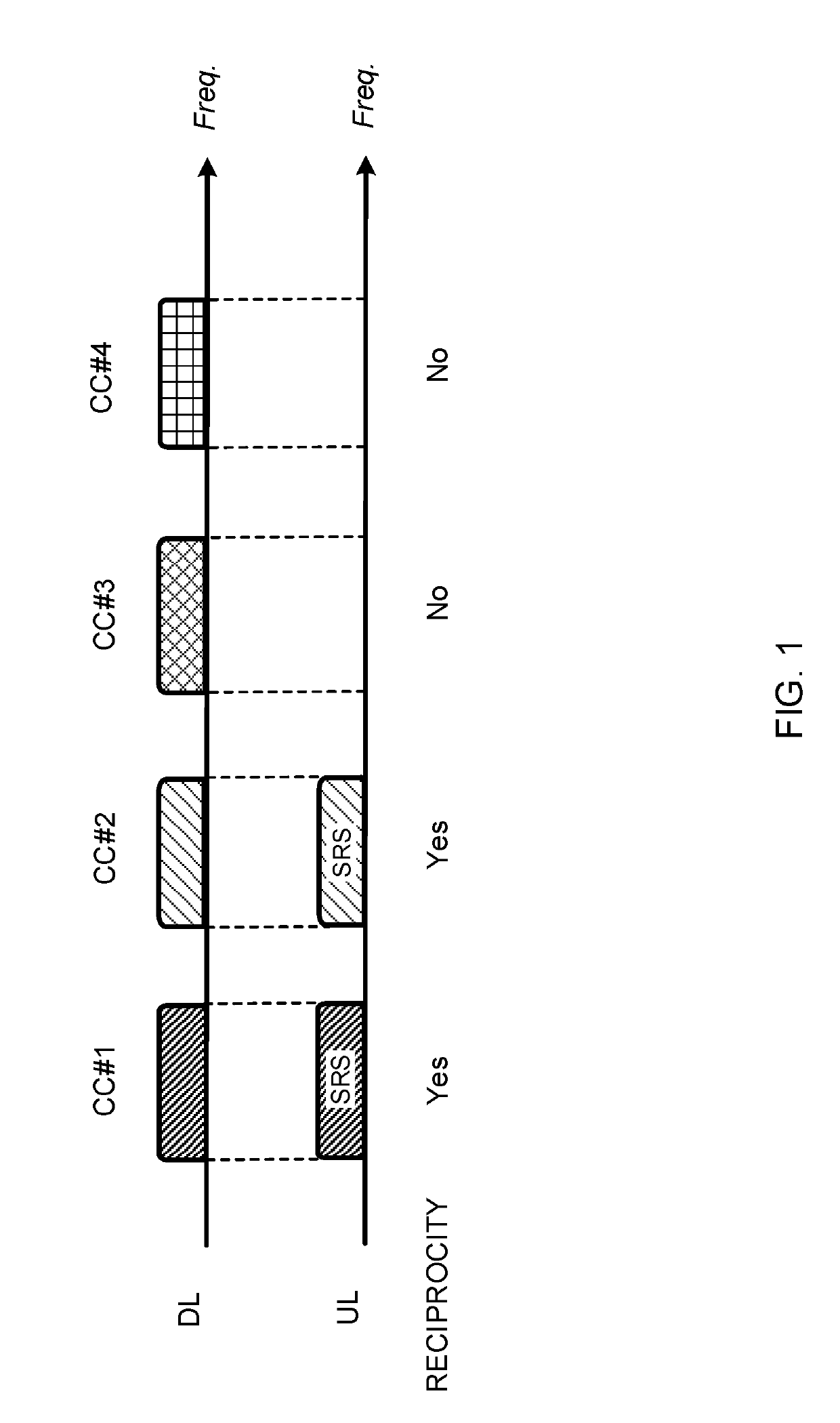
[0149]Each term that is described in this description and / or each term that is necessary to understand this description may be replaced with terms having identical or similar meanings. For example, a channel and / or a symbol may be signals (signaling). Further, a signal may be a message. A reference signal can be also abbreviated as a RS (Reference Signal), or may be also referred to as a pilot or a pilot signal depending on standards to be applied. Furthermore, a Component Carrier (CC) may be referred to as a cell, a frequency carrier and a carrier frequency.

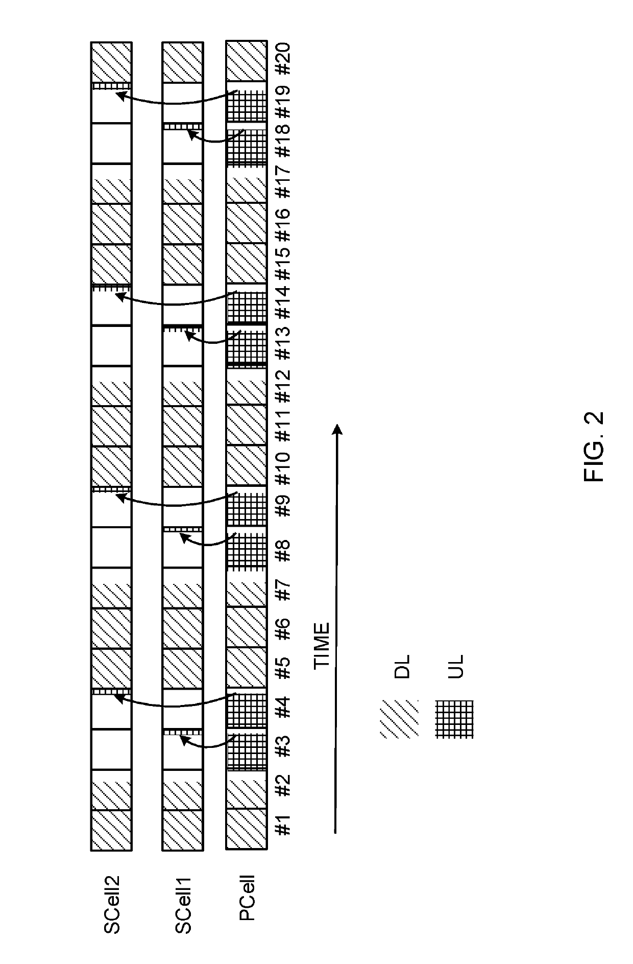
[0150]Still further, a radio frame may include one or a plurality of periods (frames) in a time domain. Each of one or a plurality of periods (frames) that composes a radio frame may be referred to as a subframe. Further, the subframe may include one or a plurality of slots in the time domain. Furthermore, the slot may include one or a plurality of symbols (Orthogonal Frequency Division Multiplexing (OFDM) symbols or Single Carr...


PUM


Abstract

Even when a temporary frequency switching technique is used by TDD, a sufficient throughput is achieved. A user terminal includes: a transmission / reception section that performs uplink transmission and / or downlink reception via a first cell; and a control section that controls the transmission / reception section to transmit capability information related to UL reference signal switching for switching the first cell to a second cell different from the first cell and transmitting a UL reference signal.

Description

TECHNICAL FIELD[0001]The present invention relates to a user terminal, a radio base station and a radio communication method of a next-generation mobile communication system.BACKGROUND ART[0002]In Universal Mobile Telecommunications System (UMTS) networks, for the purpose of higher data rates and low latency, Long Term Evolution (LTE) has been specified (Non-Patent Literature 1). For the purpose of wider bands and a higher speed than LTE (also referred to as LTE Rel. 8 or 9), LTE Advanced (also referred to LTE Rel. 10, 11 or 12) has been specified, and successor systems of LTE (also referred to as Future Radio Access (FRA), the 5th generation mobile communication system (5G), and LTE Rel. 13 and Rel. 14) have been also studied.[0003]LTE Rel. 10 / 11 have introduced Carrier Aggregation (CA) that aggregates a plurality of Component Carriers (CC) to obtain a wider band. A system band of LTE Rel. 8 is one unit that composes each CC. Further, according to CA, a plurality of CCs of the same...

Claims


Application Information

Patent Timeline
30 May 2019
Publication
US20190165908A1
IPC
H04L5/00; H04W72/04; H04L5/14
CPC
H04L5/0048; H04W72/0413; H04L5/14; H04W8/24; H04W72/04; H04W8/22; H04L5/0044; H04L5/001
Inventors
TAKEDA, KAZUKI; MATSUMURA, YUKI