
Apparatus for measuring the stiffness of mailpieces

a technology for measuring apparatuses and mailpieces, applied in the direction of material strength using steady bending force, sorting, etc., can solve the problems of not being able to distinguish between mail articles with very high inherent properties, the measurement apparatus is not able to adapt to a wide range, and the thickness of known measurement apparatuses is not large, etc., to achieve good quality, low vibration, and high accuracy.

Active Publication Date: 2019-06-06
SOLYSTIC
View PDF8 Cites 1 Cited by
  • Summary
  • Abstract
  • Description
  • Claims
  • Application Information

AI Technical Summary

Benefits of technology

The patent describes a conveyor system that prevents articles from hitting the roller and causing large shocks during the ramp up process. The system has wheels with deformable rims that generate very little vibration, and an outlet ramp that prevents the rear edge of a rigid article from hitting the deflection roller. The invention also allows very stiff articles to position themselves without shocks and flat against the inlet ramp. This results in a stiffness measurement of good quality.

Problems solved by technology

That known measurement apparatus is not adapted for a wide range of mail articles going from a standard letter to large-format flat mail articles or “flats,” such as catalogs or magazines having thick bindings.
If the radius of curvature in the curved portion of the conveyor is relatively small for reasons of compactness of the sorting installation, that can lead to deformation forces deforming the conveyor belts by stretching that are very large and that result in the mail articles being damaged under the effect of excessive force.
In addition, that measurement apparatus is not adapted for differentiating between mail articles having very high inherent stiffness such as a catalogue with a thick binding and mail articles having relative stiffness because they contain, for example, a very rigid object inside them, such as a pen or a metal plate such as a key.
However, that apparatus does not make it possible to take measurements over a wide range of mail articles of non-uniform stiffness.

Method used


Image

  • Apparatus for measuring the stiffness of mailpieces
  • Apparatus for measuring the stiffness of mailpieces
  • Apparatus for measuring the stiffness of mailpieces

Examples


Embodiment Construction

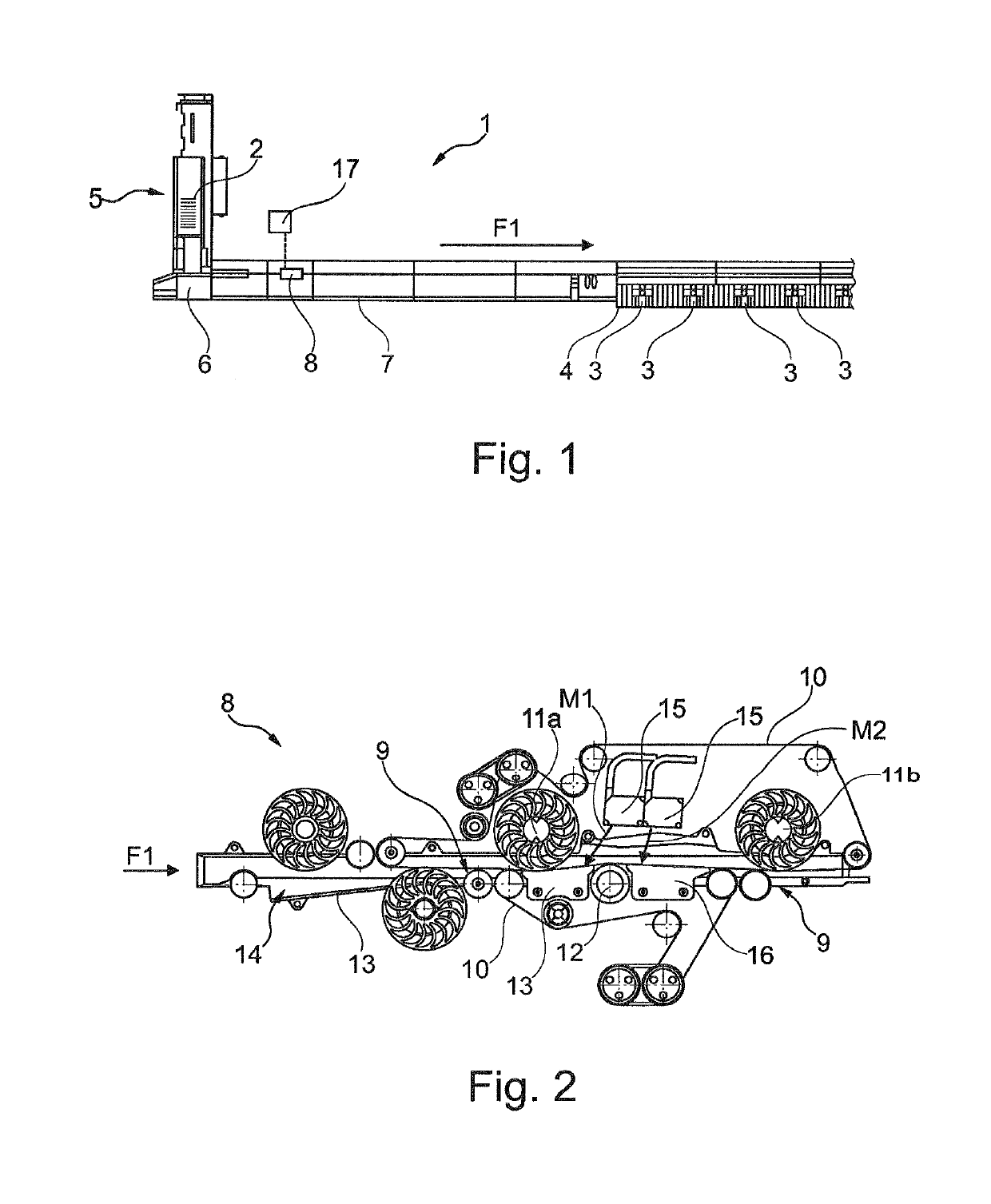
[0035]FIG. 1 is a fragmentary view of a postal sorting machine 1 designed to sort flat mail articles that are designated by reference 2 and that may be very non-uniform.

[0036]The mail articles may be very flexible, such as catalogues that are flexible but that have rigid edges, letters that are flexible but that contain rigid objects inside them (e.g. keys or pens), or indeed large-format flat articles of the type that are reinforced with cardboard or with some other rigid material, etc.

[0037]FIG. 1 shows sorting outlets 3, and a reject outlet 4 upstream from the sorting outlets 3.

[0038]The articles 2 are stacked on edge in the magazine 5 of an unstacker 6 that feeds the articles 2 in series and on edge into the sorting conveyor 7 that moves them towards the outlets 3 or 4 in a conveying direction indicated by arrow F1.

[0039]FIG. 1 also shows measurement apparatus 8 for measuring the stiffness of the articles 2.

[0040]As can be seen in FIG. 1, this measurement apparatus 8 is disposed...


PUM

PropertyMeasurementUnit
thicknessaaaaaaaaaa
thicknessaaaaaaaaaa
thicknessaaaaaaaaaa

Abstract

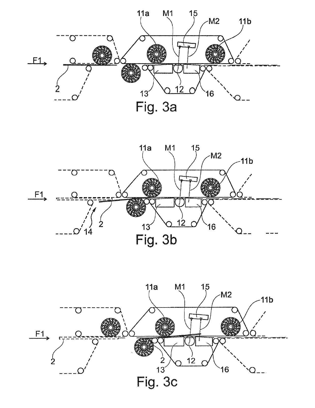
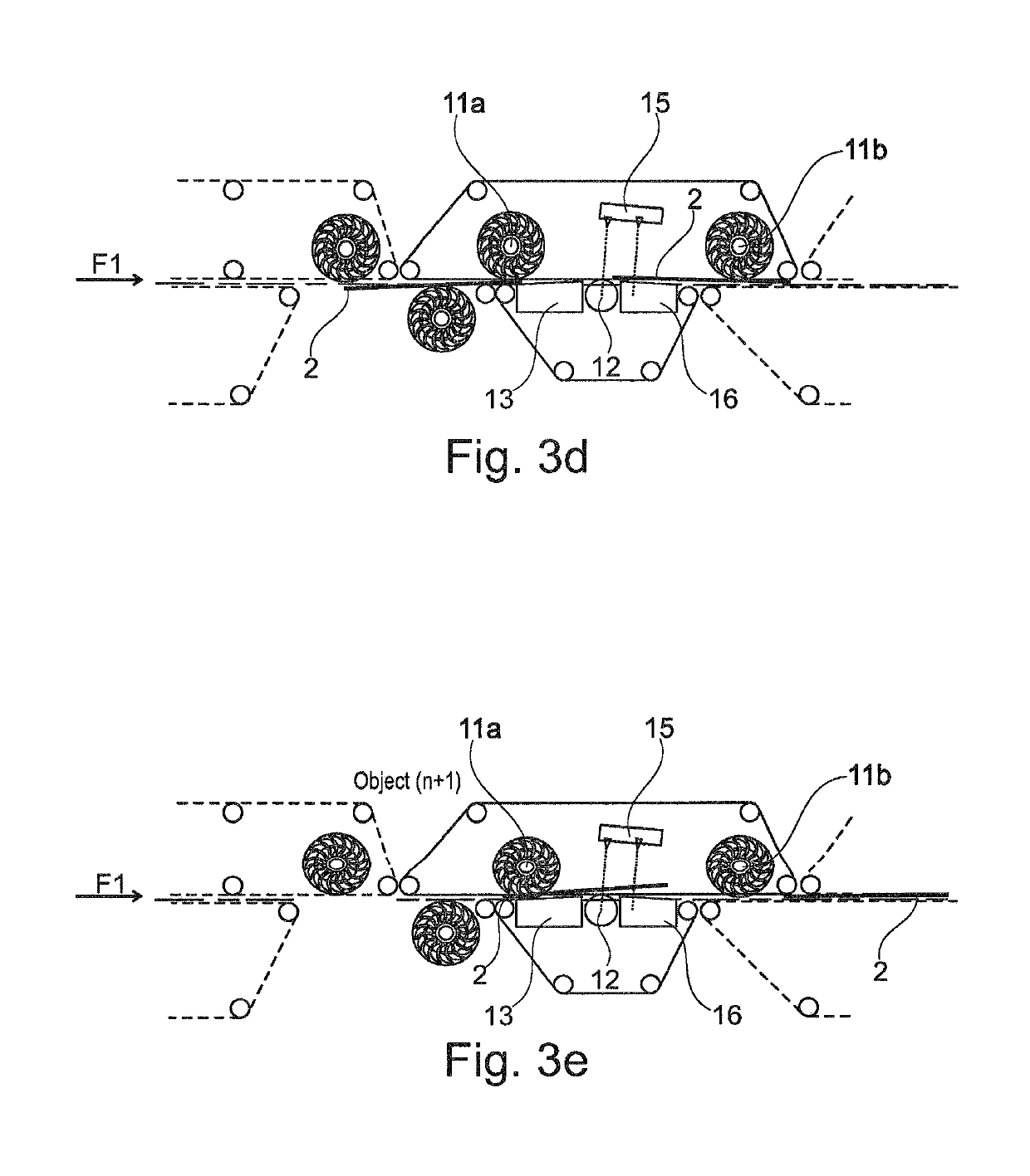
Apparatus for measuring the stiffness of mail articles on the principle of measuring deflection of a beam in bending comprises a rectilinear conveying portion for conveying the mail articles, a deflection roller disposed in a staggered offset manner between two wheels having deformable rims in such a manner as to form a substantially triangular peak on the rectilinear conveying portion, and an inlet ramp that is disposed upstream from the peak and that follows the upward slope of the peak.

Description

TECHNICAL FIELD[0001]The invention relates to measurement apparatus for measuring the stiffness of flat articles, and in particular of mail articles, which apparatus comprises a conveying portion along which the articles are conveyed in series and on edge, and a stiffness sensor operating on the principle of measuring deflection of a beam in bending, which sensor is disposed along said conveying portion for measuring in contactless manner the stiffness of each article.[0002]The invention also relates to a postal sorting machine including such apparatus for measuring the stiffness of mail articles.PRIOR ART[0003]U.S. Pat. No. 6,032,517 discloses a postal sorting machine including measurement apparatus for measuring the stiffness of mail articles conveyed in series and on edge on a sorting conveyor.[0004]In that apparatus, the stiffness measurement is taken in a curved portion of the sorting conveyor, which conveyor is a pinch belt conveyor.[0005]That stiffness measurement apparatus o...

Claims


Application Information

Patent Timeline
Patent Type & Authority Applications(United States)
IPC IPC(8): B07C1/16G01N3/20
CPCB07C1/16G01N3/20B65H2511/13B65H2701/1916
Inventor EL BERNOUSSI, HICHAMLA PAGLIA, ANTHONYTELUOB, JEAN-MARCREBOUL, JEAN-MICHELEYRAUD, FABRICE
Owner SOLYSTIC
Learn More