Installation Of Ground Loops For Geothermal Heating And/Or Cooling Applications

a technology for installing ground loops and geothermal heating and/or cooling applications, which is applied in the direction of sealing/packing, lighting and heating apparatus, and well accessories. it can solve the problems of voids, more difficult, and difficult to take ground loops or heat exchangers down into the borehol

Inactive Publication Date: 2019-06-06
DANDELION ENERGY INC
View PDF0 Cites 4 Cited by
  • Summary
  • Abstract
  • Description
  • Claims
  • Application Information

AI Technical Summary

Problems solved by technology

However, taking the ground loop or heat exchanger down into the borehole can be difficult, especially in the case of a hole that is several hundred feet deep, as both the ground loop (or heat exchanger) and the tremie pipe tend to float in the mud material left during the drilling process.
In addition, the ground loop (or heat exchanger) may tend to twist during the insertion, causing the tubing of the loop to separate and form a helix.
This can make it even more difficult for the grout to fill in the annulus between the borehole and the ground loop, and may even result “channeling” or voids (for example, air pockets).
In this regard, the borehole is not properly encased by the grout and there is a risk of underground aquifers from mixing with one another by traveling through such voids in the grout.
This is especially problematic when one aquifer is used as potable water and another includes contaminants such as iron, salts, or other materials which should not be consumed by humans.
In addition, the voids may affect the efficiency of the thermal connection between the ground loop or heat exchanger and the Earth, reducing the overall effectiveness of the geothermal heating and / or cooling system.

Method used


Image

  • Installation Of Ground Loops For Geothermal Heating And/Or Cooling Applications
  • Installation Of Ground Loops For Geothermal Heating And/Or Cooling Applications
  • Installation Of Ground Loops For Geothermal Heating And/Or Cooling Applications

Examples


Embodiment Construction

Overview

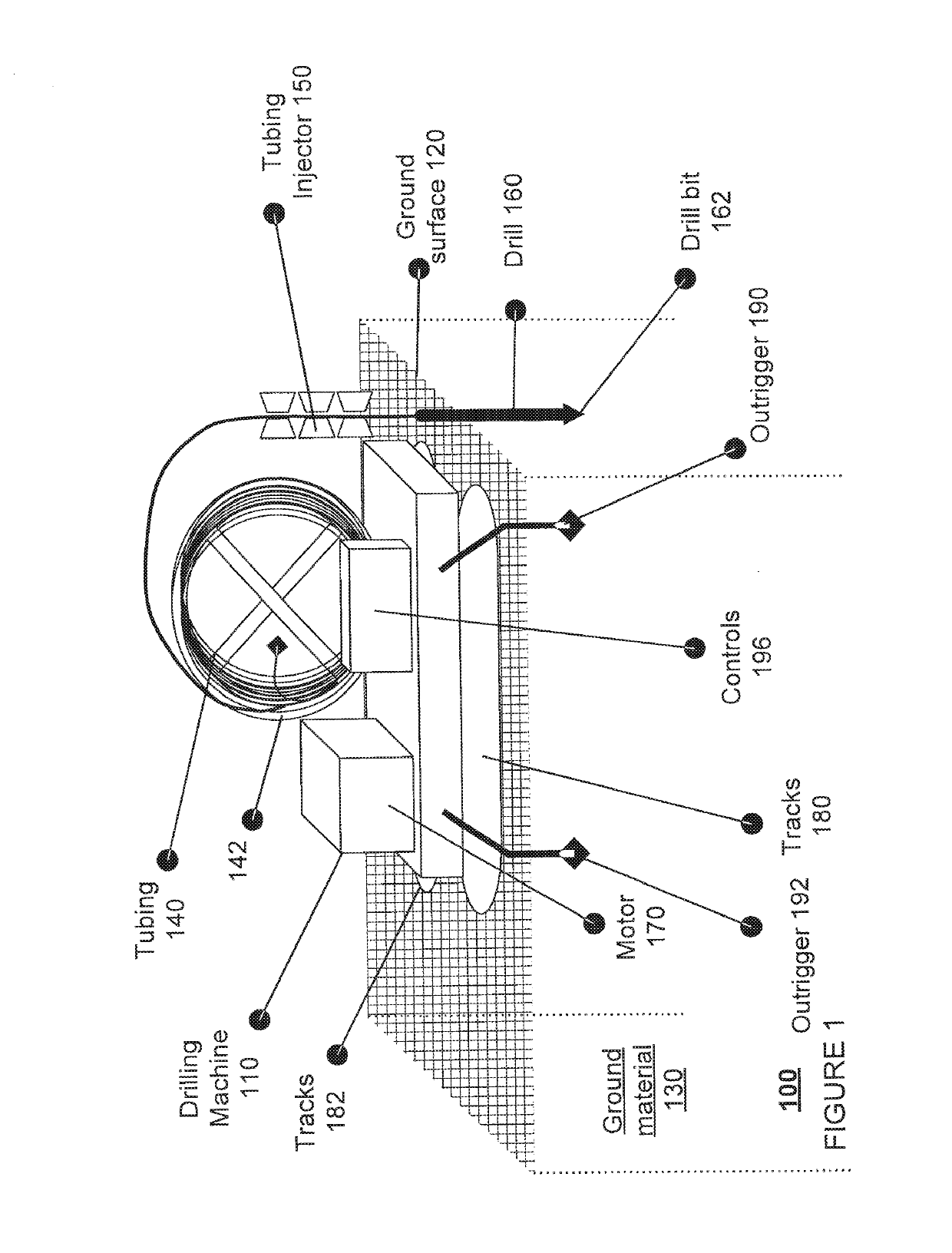
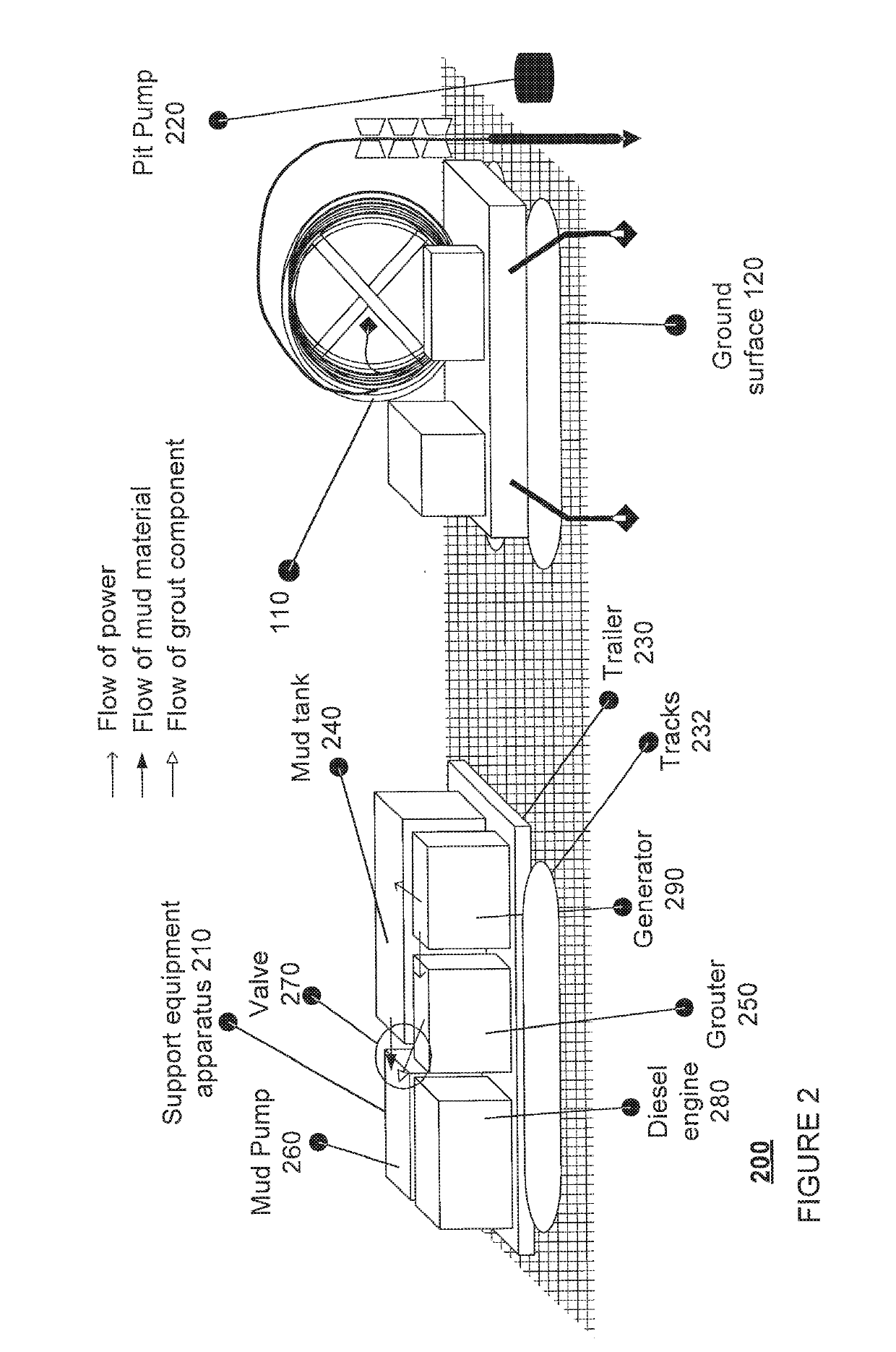
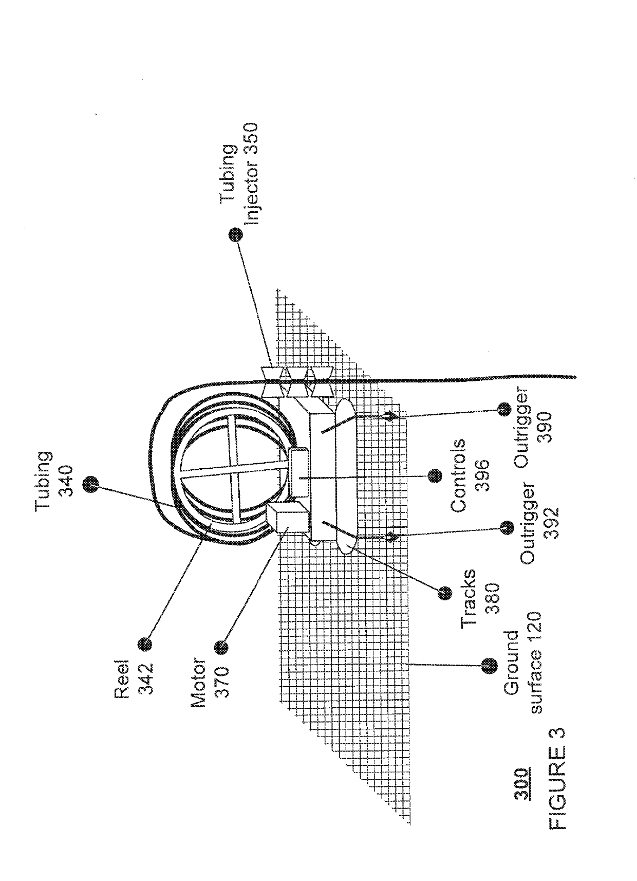
[0020]Aspects of the technology relate installing a ground loop for a geothermal heating and / or cooling system, such as those used to heat and cool various structures. For instance, an example system may include a drilling machine, an equipment support apparatus, and a heat exchanger insertion apparatus. The drilling machine may include a coil of tubing. A first end of the tubing may be configured with a drill such as a downhole drilling mud motor or downhole hammer with an attached drill bit. The drilling machine may also include or be connectable with a tubing injector which can be clamped around the tubing in order to straighten the tubing and to orient the tubing into a borehole created by the hammer.

[0021]The drilling machine also includes a drive system configured to control the extension and retraction of the tubing. In this regard, the drive system may rotate a reel upon which the tubing is wrapped. The drive system may also control movement of the drilling machine, ...


PUM


Abstract

In order to install a ground loop for a geothermal heating and / or cooling system in ground material, a drilling machine having a drill bit connected to an end of first tubing may be used to create an borehole in the ground material. After the borehole is created, grout may be pumped into the borehole through the first tubing as the first tubing is removed from the borehole. This allows the borehole to be grouted from the bottom towards the top. Thereafter, second tubing may be inserted into the grout in order to create the ground loop. This eliminates the need for a “tremie” pipe to insert the ground loop and pump grout into the borehole, while still allowing for the borehole to be grouted from the bottom towards the top to reduce the likelihood of voids.

Description

CROSS-REFERENCE TO RELATED APPLICATIONS[0001]The present application claims the benefit of U.S. Provisional Application No. 62 / 595,315 filed Dec. 6, 2017 for “Installation of Ground Loops for Geothermal Heating and / or Cooling Applications”, which is incorporated herein by reference.BACKGROUND[0002]Geothermal heating and / or cooling systems include one or more ground loops for exchanging heat with ground material. These ground loops can be arranged horizontally or vertically. Installation of vertical ground loops typically involves drilling an opening or “borehole” in the ground material to a desired depth using a mud material to encase the borehole. Thereafter, inserting a ground loop or heat exchanger and “tremie” pipe are into the borehole. Once in position, grout is deposited into the borehole from the bottom towards the top via the tremie pipe as the tremie pipe is pulled upwards and removed from the borehole. The grout, which is typically selected to enhance thermal conductivity...

Claims


Application Information

Patent Timeline
Patent Type & Authority Applications(United States)
IPC IPC(8): E21B33/14E21B7/00E21B7/02F24T10/13
CPCE21B33/14E21B7/003E21B7/02F24T10/13F24T2010/53E21B7/026E21B7/027E21B19/22Y02E10/10
Inventor HATALSKY, OLIVIAJOHNSON, HOWARD E.KALE, AMIT
Owner DANDELION ENERGY INC
Why Eureka
Try Eureka