Post Barrel Plenum Operated Gas Cycling System for Automatic Firearms

a technology of automatic firearms and gas cycling, which is applied in the field of automatic gas operated firearms, can solve the problems that current gas operated repeating firearms do not offer the same accuracy and velocity as bolt action firearms, and achieve the effects of reducing the sound of the shot, improving accuracy, and cleaning the operation

Active Publication Date: 2019-06-06
RHINO PRECISION LLC
View PDF0 Cites 5 Cited by
  • Summary
  • Abstract
  • Description
  • Claims
  • Application Information

AI Technical Summary

Benefits of technology

[0005]The present invention does not require a vertical port hole in the barrel. This eliminates the inconsistency in the barrel and reduces bullet vibration, thus adding accuracy. The gas port hole is instead located in the buffer plenum of the present invention, past the end of the barrel rifling. The bullet leaves the rifling before the gas enters the plenum and is thereafter directed down the gas tube. The bullet is no longer in contact with rifling when the gas is drawn away and directed to the receiver and bolt. The bolt starts to open after the bullet is out of rifling contact. This allows for consistent gas pressure on the bullet throughout barrel travel on every shot. Consistent gas pressure generates increased and consistent velocity and thus adds accuracy. Because the gas port hole is located in the buffer plenum of the present invention, past the end of the rifling, the system allows for more of the powder to be burned before it is directed to the bolt. This reduces fouling and allows for longer operation between cleanings.
[0006]The buffer plenum of the present invention has multiple chambers. This causes the plenum to act like a capacitor as the bullet travels through. The multiple chambers store pressure that is consistently applied into the gas tube and to the bolt as the bullet passes through the chambers. This greatly reduces cycling issues with different rounds and barrel lengths. The end of barrel gas buffer plenum of the present invention is an improvement on the typical gas cycling mechanism for automatic firearms. Current gas operated repeating firearms do not offer the same accuracy and velocity as do bolt action firearms. The present invention allows the same or similar accuracy and velocity from a gas operated repeating firearm as that of a bolt action firearm. The system of the present invention further helps reduce the amount of fouling of the bolt as occurs in other gas operated firearms.
[0008]The target side end cap of the present invention is designed to allow the bullet to leave the buffer plenum and retain as much gas as possible in the plenum enclosure without contacting the bullet. The diameter of the central hole in the target side end cap should be as close to the bullet diameter as possible without allowing contact with the bullet as it passes through. This ensures as much gas pressure as possible is retained in the plenum for as long as possible. Avoiding contact with the bullet ensures maximum accuracy. The target side end cap may be attached to the rest of the plenum assembly by any method, not limited to the following: threaded, welded, bolted, snap-on, quick attach, clamp etc. The target side end cap may be fabricated from, but not limited to, steel, stainless steel, titanium, aluminum, polymer, ceramic, Inconel, etc.
[0016]The components of the system of the present invention could be reconfigured by changing the number of chamber walls in the assembly, and thus the length of the plenum tube. The plenum tube may also be eliminated and the chamber walls may be fixed together in series by welding, bolting or threading so that they generate the same concentric line of chambers required for operation. The gas tube hole may be positioned in any chamber space from any direction. Repositioning of the gas tube hole to an alternate end cap or plenum tube location can change the aesthetics and the performance of the bolt cycling function. The components may also interface with a gas tube back to the bolt, or reconfigured with a piston shaft that contacts the bolt. The barrel of the firearm may itself be machined to eliminate the need for a barrel side end cap, with the plenum tube being formed as part of the barrel. The barrel could also have a gas tube gun drilled into it to transmit the gas back from the plenum tube.
[0019]The end of barrel gas buffer plenum may also be modified with additional baffles and materials to form an integrated suppressor. This would dramatically reduce the sound of the shot, and still function to cycle the firearm.
[0020]Any gas operated firearm could benefit from the present invention. The end of barrel gas buffer plenum may be designed onto the end of the barrel of any new firearm, and connected to the receiver with the standard gas tube or piston. Alternately, the plenum may be retrofitted to any existing gas operated firearm. The system would benefit by increased accuracy, cleaner operation and more robust cycling of the firearm.

Problems solved by technology

Current gas operated repeating firearms do not offer the same accuracy and velocity as do bolt action firearms.

Method used


Image

  • Post Barrel Plenum Operated Gas Cycling System for Automatic Firearms
  • Post Barrel Plenum Operated Gas Cycling System for Automatic Firearms
  • Post Barrel Plenum Operated Gas Cycling System for Automatic Firearms

Examples


Embodiment Construction

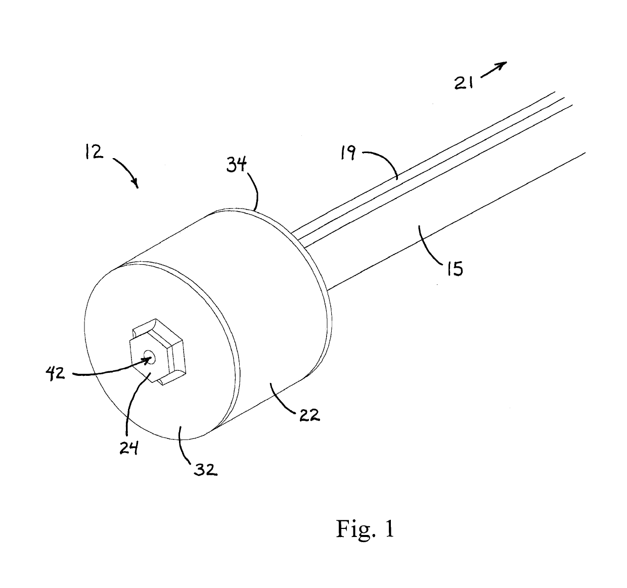
[0037]Reference is made first to FIG. 1 which is a perspective view of a first preferred embodiment of the system of the present invention implemented on the end of a typical firearm barrel, removed from the associated firearm for clarity. Gas cycling system 10 in the first preferred embodiment includes end of barrel gas buffer plenum 12 positioned on the end of firearm barrel 15 and connected to the weapon receiver by way of gas tube 19. Gas buffer plenum 12 is shown to generally comprise plenum tube 22 with target side end cap 32. Centered in end cap 32 is hexagonal shaped exit port 24 suitable for facilitating the rotation of gas buffer plenum 12 onto the threaded end of a typical firearm barrel. Gas tube 19 shown in FIG. 1 extends from a return port (not seen in this view) positioned on the barrel side of gas buffer plenum 12 and directs the collected pressurized gas from the gas buffer plenum 12 to conduct it back to the receiver of the weapon, whereby the high pressure gas may...


PUM


Abstract

A gas buffer plenum positioned at the end of the barrel of an automatic firearm. A barrel side end cap connects the system to the barrel. A plenum tube holds one or more chamber walls and retains gas pressure within the enclosure. A target side end cap creates the final pressure chamber enclosure and is attached to the plenum tube to lock the system together. This gas buffer plenum allows a bullet to leave the barrel of the firearm before the bolt of the firearm starts to open. As the gas buffer plenum is filled with the exploding gas behind the bullet, the gas chambers build and maintain pressure that is then forced back through a hole in the plenum. The gas is forced down a gas tube or into a piston system. Depending on the configuration of the firearm, either the gas force, or the piston, strikes the bolt and cycles the firearm. The system may also be used to retrofit a gas operated firearm that uses a traditional gas block design.

Description

CROSS REFERENCES TO RELATED APPLICATIONS[0001]This Application claims the benefit under Title 35 United States Code § 120, as a Continuation (Divisional) of co-pending U.S. patent application Ser. No. 14 / 681,031, filed Apr. 7, 2015, which claims the benefit under Title 35 United States Code § 119(e) of U.S. Provisional Application 61 / 975,987, filed Apr. 7, 2014, the full disclosures of which are incorporated herein by reference.BACKGROUND OF THE INVENTION1. Field of the Invention[0002]The present invention relates generally to firearms and more specifically to automatic gas operated firearms. The present invention provides a gas buffer plenum at the end of a firearm barrel that stores and directs high pressure gas through a gas tube to the receiver of the firearm in order to cycle the bolt after the bullet has left contact with the barrel rifling.2. Description of the Related Art[0003]Most currently available automatic gas operated firearms have a barrel with a small hole drilled ve...

Claims


Application Information

Patent Timeline
Patent Type & Authority Applications(United States)
IPC IPC(8): F41A5/26
CPCF41A5/26F41A5/28
Inventor KINGSBURY, KLINT MCLEANREINARZ, CLAYTON WARRENSNIDER, RONALD CHRISTOPHER
Owner RHINO PRECISION LLC
Why Eureka
Try Eureka