
Verification system, verification method, and recording medium for storing verification program

a verification system and verification method technology, applied in the field of verification systems, can solve the problems of affecting the design of the event generation process, the designer is difficult to predict the amount of data to be processed, and the load deviation from the created distribution does not meet a predetermined non-functional requirement,

Inactive Publication Date: 2019-06-06
NEC CORP
View PDF0 Cites 1 Cited by
  • Summary
  • Abstract
  • Description
  • Claims
  • Application Information

AI Technical Summary

Benefits of technology

The invention allows for the mathematical proof that the system can handle the load of traffic that is likely to happen. This means that the system is designed to perform well no matter what kind of traffic it receives.

Problems solved by technology

However, at the time of system design, it is difficult for the designer to predict the event generation timing or the amount of data to be processed.
In other words, it is difficult for the designer to predict the load on the calculation process at the time of system design.
Even when by using the above-mentioned alternative method, it is determined that the non-functional requirement is satisfied, there is a possibility that the load deviated from the created distribution does not satisfy a predetermined non-functional requirement.
When the system having the non-functional requirement of which there is a possibility that the load which does not satisfy the predetermined non-functional requirement exists is used, an incident that has an influence on the real world may occur.
Therefore, the system performance to the arrival load that is not sampled is not guaranteed completely.
On the other hand, when the infinitely small step size is used, the number of times of calculation increases to infinite and the simulation cannot be carried out.
Therefore, in principle, it is impossible to perform the simulation to all the values that can be taken by the variable included in a function.

Method used


Image

  • Verification system, verification method, and recording medium for storing verification program
  • Verification system, verification method, and recording medium for storing verification program
  • Verification system, verification method, and recording medium for storing verification program

Examples


first example embodiment

[0036][Description of Configuration]

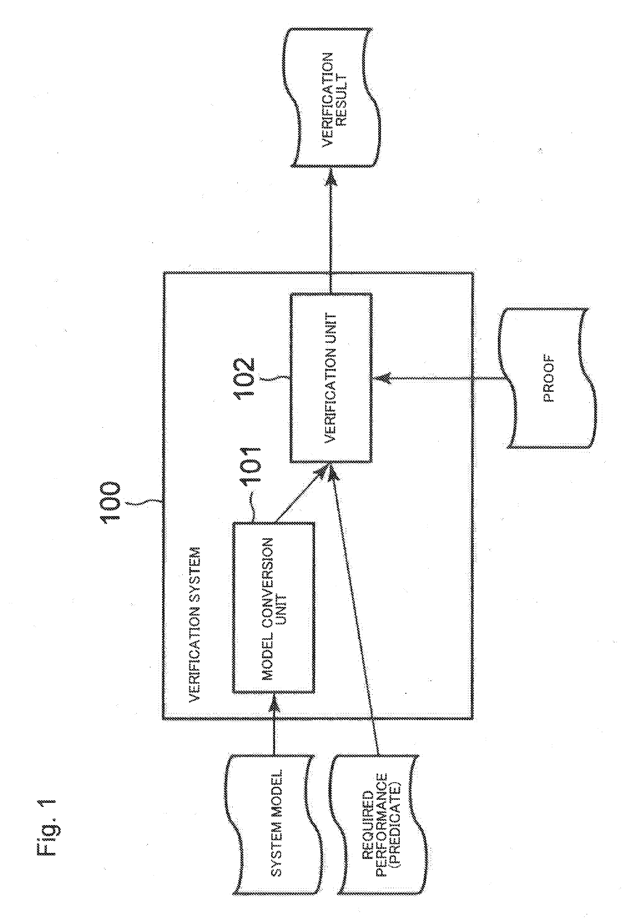
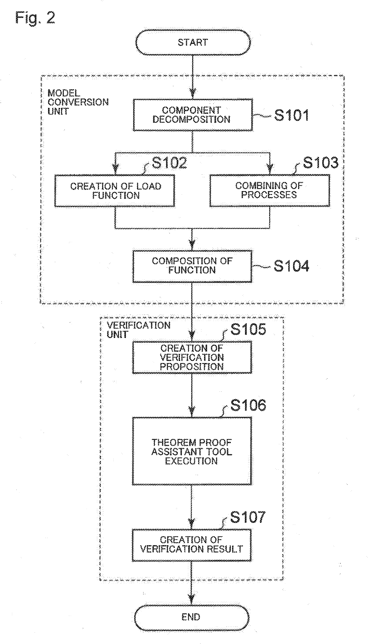
[0037]An example embodiment of the present invention will be described below with reference to the drawings. FIG. 1 is a block diagram illustrating an example of a configuration of a verification system 100 according to a first example embodiment. As shown in FIG. 1, the verification system 100 according to the present example embodiment includes a model conversion unit 101 and a verification unit 102.

[0038]The model conversion unit 101 has a function to create a load function on the basis of a system model. For example, an activity diagram in which the system model is described is inputted to the model conversion unit 101.

[0039]The activity diagram is a diagram indicating a transition of successive processes. In the activity diagram, the processes performed from the beginning to the end of a predetermined event are described in order of execution. The activity diagram is described in, for example, SysML.

[0040]Further, the activity diagram may be ...

second example embodiment

[0068][Description of Configuration]

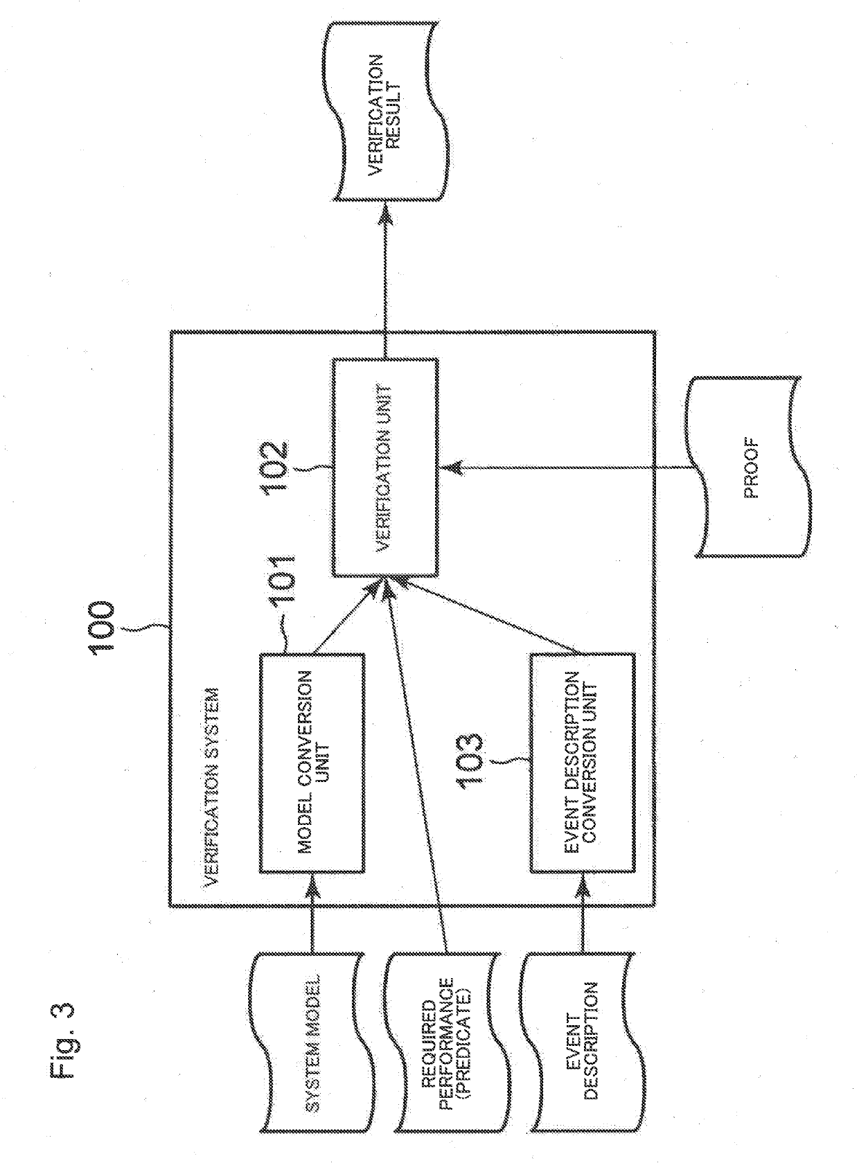
[0069]Next, a second example embodiment of the present invention will be described with reference to the drawings. FIG. 3 is a block diagram illustrating an example of a configuration of the verification system 100 according to the second example embodiment. As shown in FIG. 3, the verification system 100 according to the present example embodiment includes the model conversion unit 101, the verification unit 102, and an event description conversion unit 103. The configuration of the verification system 100 shown in FIG. 3 excluding the event description conversion unit 103 is similar to the configuration of the verification system 100 shown in FIG. 1.

[0070]An event description is inputted to the event description conversion unit 103. The event description conversion unit 103 has a function to convert the inputted event description into a time series of probabilities of arrival load.

[0071]The predicate representing the required performance combine...


PUM


Abstract

A verification system includes at least one memory configured to store instructions; and at least one processor configured to execute the instructions to: receive, as input, a mathematical model obtained by converting a model indicating a configuration of a test object system into a predicate in predicate logic and create a proposition indicating that the test object system satisfies a performance requirement represented by the predicate; and verify whether or not a proof of the proposition having been created is true.

Description

TECHNICAL FIELD[0001]The present invention relates to a verification system or the like that verifies a non-functional requirement of a system.BACKGROUND ART[0002]There is a system in which a control process is performed after measuring information in a real world environment by a sensor (sensing) and performing a calculation process on data obtained through the sensing. When a result of control performed by the system has a large influence, a designer is required to carefully perform design, development, and verification of the system.[0003]In general, a system requirement is categorized into a functional requirement and a non-functional requirement. The functional requirement is a requirement related to a function among requirements defined in information system development or software development. The functional requirement includes requirements related to type of data to be treated or structure, processing content, screen display format, operation method, output format of a form...

Claims


Application Information

Patent Timeline
IPC IPC(8): G06N7/00G06N5/04
CPCG06N7/00G06N5/045G06F11/3447G06F11/3452G06N5/01G06F11/34
Inventor FUNAKOSHI, KAZUHIRO
Owner NEC CORP
Learn More