
Pneumatic tire and structure for securing electronic part to tire

a technology of pneumatic tires and electronic parts, which is applied in the direction of tyres, vehicle components, tire measurements, etc., can solve the problems of not allowing information pertaining to the tire itself to be sensed, the tire stands to suffer a loss of endurance, etc., to achieve the effect of improving endurance, reducing the deformation or bending of the inner surface of the tire, and reducing the deformation or bending

Active Publication Date: 2019-06-13
TOYO TIRE & RUBBER CO LTD
View PDF17 Cites 2 Cited by
  • Summary
  • Abstract
  • Description
  • Claims
  • Application Information

AI Technical Summary

Benefits of technology

The present invention provides a way to secure an electronic part to a tire without damaging its durability. This is achieved by using a cushioning material that is applied to the tire inner surface where the electronic part is present. The cushioning material prevents any bending or deformation of the tire inner surface, which prevents the sheet used to secure the electronic part from detaching. This improves the strength with which the electronic part is secured to the tire. Additionally, the cushioning material can surround the electronic part without the need to secure it directly to the tire inner surface, which improves the endurance of the tire.

Problems solved by technology

However, in situations such as at Japanese Patent Application Publication Kokai No. 2012-240465 and International Patent Application Publication No. 2009 / 13269 in which the structure is such that a foreign object is embedded in the tire inner surface, while this is advantageous in that, as there is little chance that that the foreign object will become detached from the tire, it is possible to ensure that the strength with which this is secured thereto will be adequate, there is a risk that cracking will occur, this being initiated from the site of the foreign object, as a result of which the tire stands to suffer a loss in endurance.
And with a constitution such as that at International Patent Application Publication No. 2013 / 50711 in which an electronic part and the tire inner surface are separated by means of a separating element while being secured by means of an adhering element, this is disadvantageous in that it does not permit information pertaining to the tire itself to be sensed.

Method used


Image

  • Pneumatic tire and structure for securing electronic part to tire
  • Pneumatic tire and structure for securing electronic part to tire
  • Pneumatic tire and structure for securing electronic part to tire

Examples


Embodiment Construction

Pneumatic Tire

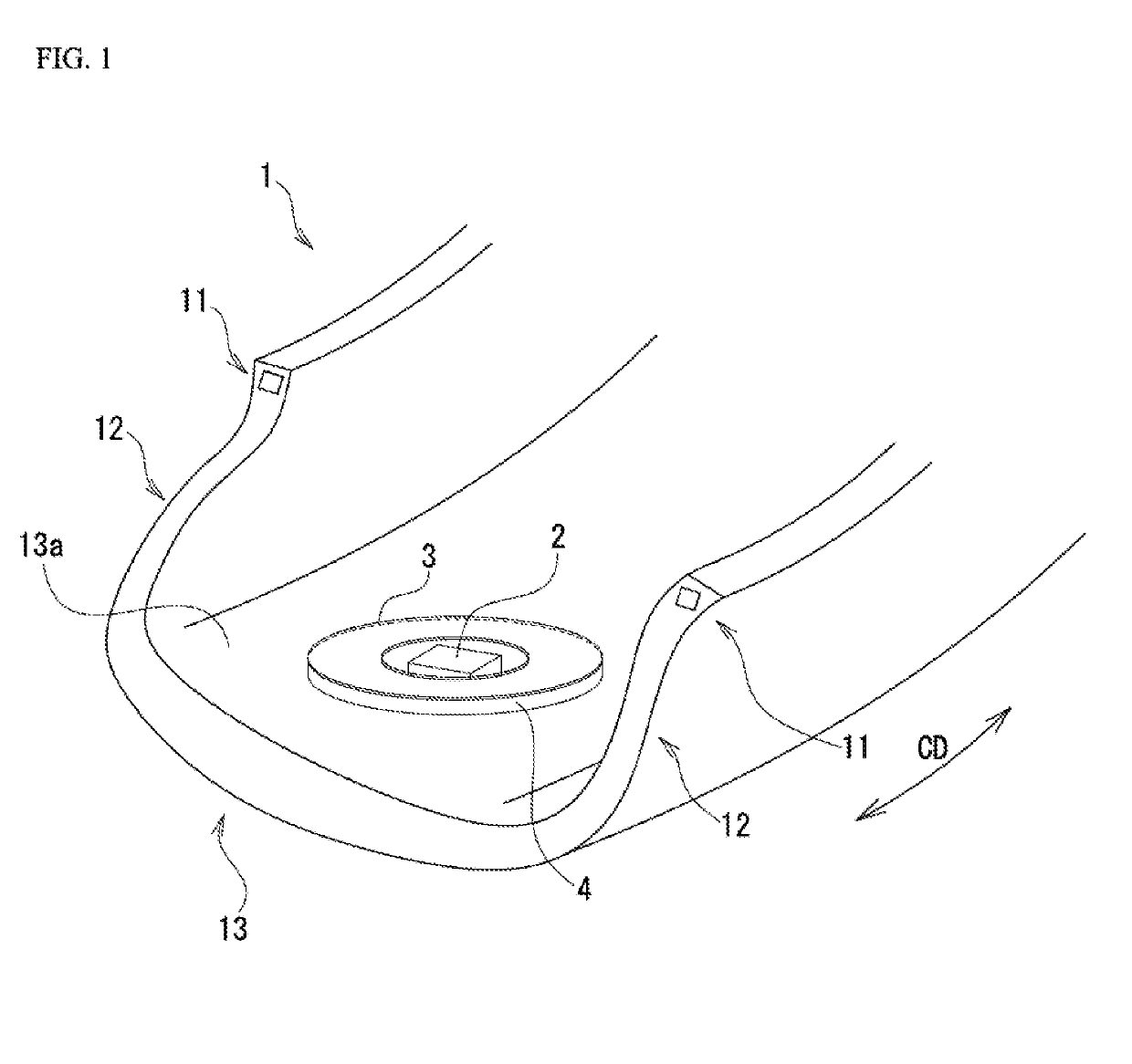
[0025]Below, embodiments of the present invention are described with reference to the drawings. FIG. 1 is a perspective view showing an example of a pneumatic tire.

[0026]As shown in FIG. 1, pneumatic tire 1 is provided with a pair of annular bead regions 11, sidewall regions 12 which extend toward the exterior in the tire radial direction from those respective bead regions 11, and a tread region 13 which is contiguous with the respective outer ends in the tire radial direction of those sidewall regions 12.

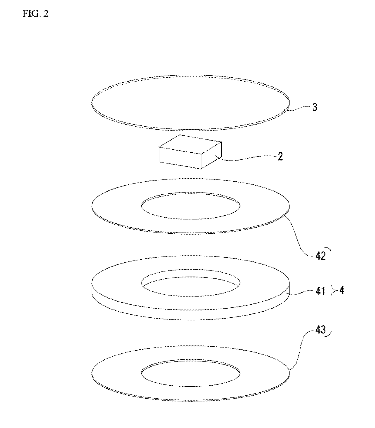
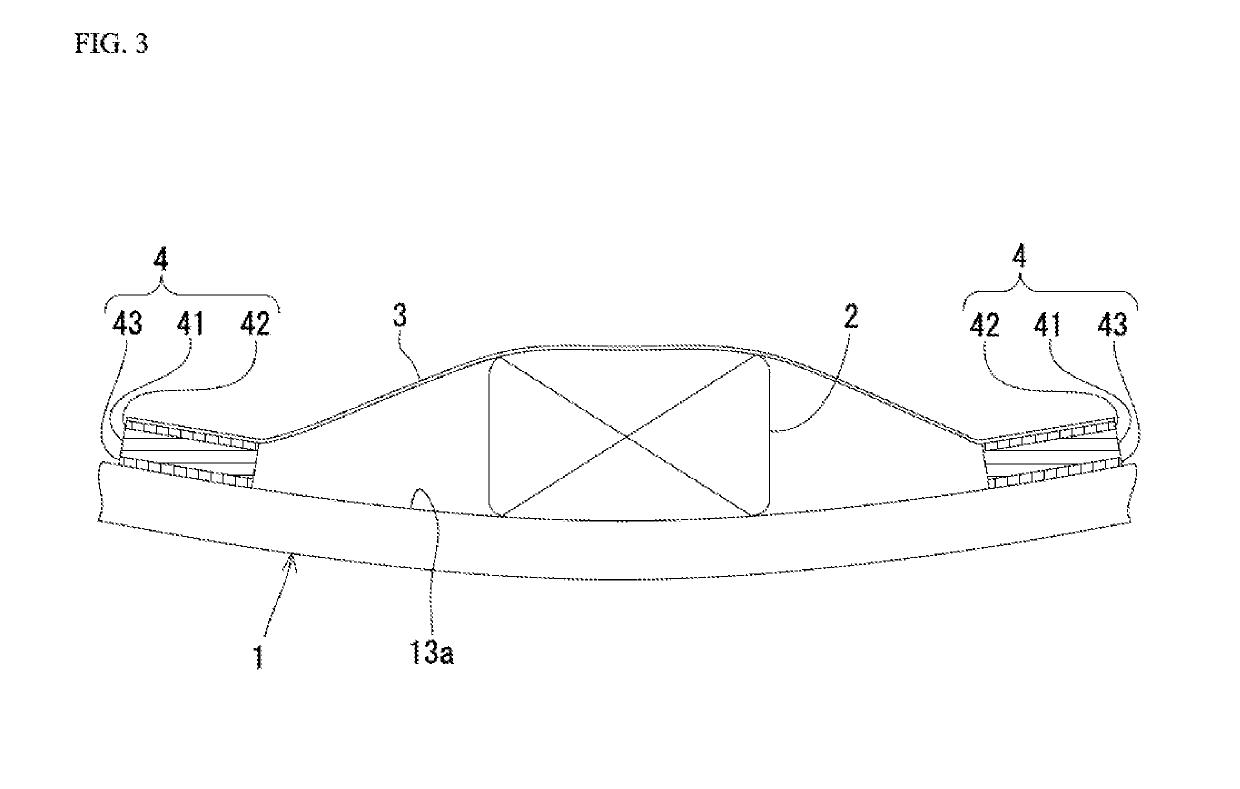
[0027]Pneumatic tire 1 has a structure for securing an electronic part to a tire at which electronic part 2 is secured to an inner surface 13a of a tread region. The securing structure has a sheet 3 for securing an electronic part 2 which is arranged between tread region inner surface 13a constituting the tire inner surface and electronic part 2, and cushioning material 4 which is arranged about the periphery of electronic part 2 and which adheres to tire inner surfac...


PUM


Abstract

A structure for securing an electronic part to a tire, has a sheet for securing the electronic part which is arranged between the sheet and a tire inner surface; and cushioning material which is arranged about a periphery of the electronic part and which adheres to the sheet and the tire inner surface. The cushioning material is not arranged on the tire inner surface where the electronic part is present but surrounds the electronic part completely or surrounds the electronic part except for at least one gap smaller than the electronic part.

Description

BACKGROUND OF THE INVENTIONField of the Invention[0001]The present disclosure relates to a pneumatic tire and to a structure for securing an electronic part to a tire at which an electronic part is properly attached to an inner surface of a tread region.Description of the Related Art[0002]Studies have been performed in recent years regarding the attachment of objects having various functions to inner surfaces of pneumatic tires.[0003]Japanese Patent Application Publication Kokai No. 2012-240465, for example, discloses art whereby one of a pair of mechanical fasteners comprising hook(s) or snap(s) is embedded in the inner surface of a tire so as to permit an object such as an electronic part comprising a sensor to be secured to the tire inner surface by way of the fastener.[0004]International Patent Application Publication No. 2009 / 13269 discloses art whereby one side of a surface fastener made up of a hook side and a loop side is embedded in the inner surface of a tire so as to perm...

Claims


Application Information

Patent Timeline
Patent Type & Authority Applications(United States)
IPC IPC(8): B60C23/04
CPCB60C23/0493B29D2030/0072
Inventor SAKAKIBARA, KAZUHIRO
Owner TOYO TIRE & RUBBER CO LTD
Learn More