System For Capturing the Energy of Fluid Currents

Active Publication Date: 2019-06-13
SAIZ MANUEL M
View PDF12 Cites 4 Cited by
  • Summary
  • Abstract
  • Description
  • Claims
  • Application Information

AI Technical Summary

Benefits of technology

[0051]The weight of the turbine and moving parts is balanced with the upward displacement of the water or air being discharged keeping the turbine horizontally positioned, except when the stream of water or air has a certain vertical inclination. However, if we want it to be tilted upwards by having its supports on the ground, or tilted downwards when they are near the surface, the weight of the turbine must be altered to achieve this. You can use turbines which are more or less the same density as the fluid, resulting in inclination which has minimal effect on the very high performance level. This may be necessary in order to avoid disrupting the navigation of ships, airplanes, etc.
[0052]It is accordingly an object of the invention to harness wave and wind energy having at least one axial turbine with a density of between 70% and 130% of that of the current in which it is moving with one end of the turbi

Problems solved by technology

Water current energy harnessing systems in the sea need complex technologies and demand high expenditure to achieve optimum performance.
They are hard to control, complex, need to be positioned in the direction of the currents and their energy is difficult to store.
These are also intricate and difficult to manage

Method used


Image

  • System For Capturing the Energy of Fluid Currents
  • System For Capturing the Energy of Fluid Currents
  • System For Capturing the Energy of Fluid Currents

Examples


Embodiment Construction

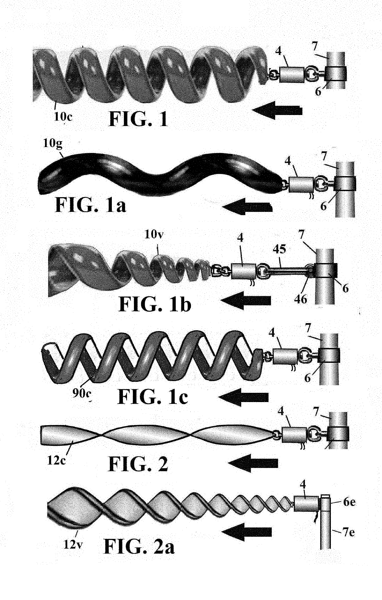
[0138]FIG. 1 shows an depiction of a turbine of the invention, formed by a helical spring (10c), which has its end held to the axis of the electric generator (4). The generator is held by means of rings to the collar (6), in turn connected to the mast (7), so that it allows it to be tilted or turned horizontally and vertically slightly, but not to rotate around said rings.

[0139]FIG. 1a shows the turbine formed by a stretched helical spring portion (10g), which has its end held to the axis of the electric generator (4). The generator is held by means of rings to the collar (6), in turn connected to the mast (7), so that it allows it to be tilted or to rotate horizontally and vertically slightly but not to rotate around said rings.

[0140]FIG. 1b shows the turbine formed by a conical coil spring (10v), which has its end held to the axis of the electric generator (4). The generator is held by the rod (45) hinged with the hinge (46) to the collar (6) of the mast (7) so that it allows it t...


PUM


Abstract

A system for capturing the energy of fluid currents, using axial turbines with one free end and the other end fastened to a mechanical element or electric generator, characterized in that the turbines comprise coil springs, helically twisted plates or crossbeams, complete helical turbines with their shafts or just their blades, which capture the energy of wind or water, with their shaft or fastened end actuating an electric generator or mechanical system. In all cases the blades around the rotation axis of the turbines have an inclination such that they generate a torque in the same direction and the turbines are automatically oriented by the water or air currents, like weather vanes.

Description

CROSS REFERENCE TO RELATED APPLICATIONS[0001]This application claims the benefit of PCT / ES2017 / 000101, filed Aug. 30, 2017, which claims the benefit of Spanish patent application number U201700535, filed Jun. 23, 2017, Spanish patent application number P201700136, filed Feb. 15, 2017, and Spanish patent application number P201600696, filed Aug. 9, 2016 the disclosure of which is incorporated herein by reference in their entirety.BACKGROUND OF THE INVENTIONa) Field of the Invention[0002]Wind, river and sea energy collectors consisting of both mini and mega-systems which function to generate large amounts of electricity. Also for housing, agriculture, seawater desalination, water pumping, supplying power to the electricity network, obtaining hydrogen by electrolysis of the water and storage of pressurized air in bags in the sea at great depth.b) Description of the Related Art[0003]Water current energy harnessing systems in the sea need complex technologies and demand high expenditure ...

Claims


Application Information

Patent Timeline
IPC IPC(8): F03B13/10F03B17/06
CPCF03B13/10F03B17/061F05B2210/11F05B2220/706F05B2240/243F03D1/06F05B2250/25F05B2210/16Y02E10/20Y02E10/30Y02E10/72F05B2240/9176Y02E10/728F03B13/22F03B13/12
Inventor SAIZ, MANUEL M.
Owner SAIZ MANUEL M
Why Eureka
Try Eureka