Driving part for variable-capacity compressor

Inactive Publication Date: 2019-06-13
HANON SYST
View PDF14 Cites 2 Cited by
  • Summary
  • Abstract
  • Description
  • Claims
  • Application Information

AI Technical Summary

Benefits of technology

[0021]A drive unit for a variable capacity compressor according to exemplary embodiments of the present invention has an effect of main

Problems solved by technology

However, this hinge mechanism requires the process of press-fitting the rotor to the rotary shaft, thereby causing complexity of work processes and product structures.
Hence, the drive unit is disadvantag

Method used


Image

  • Driving part for variable-capacity compressor
  • Driving part for variable-capacity compressor
  • Driving part for variable-capacity compressor

Examples


Embodiment Construction

[0027]Hereinafter, a drive unit for a variable capacity compressor according to exemplary embodiments of the present invention will be described in detail with reference to the accompanying drawings.

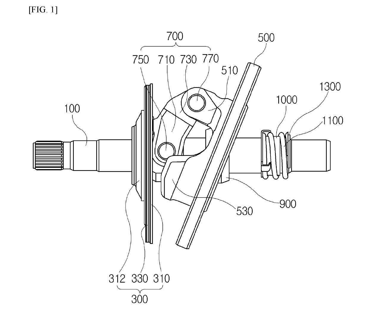
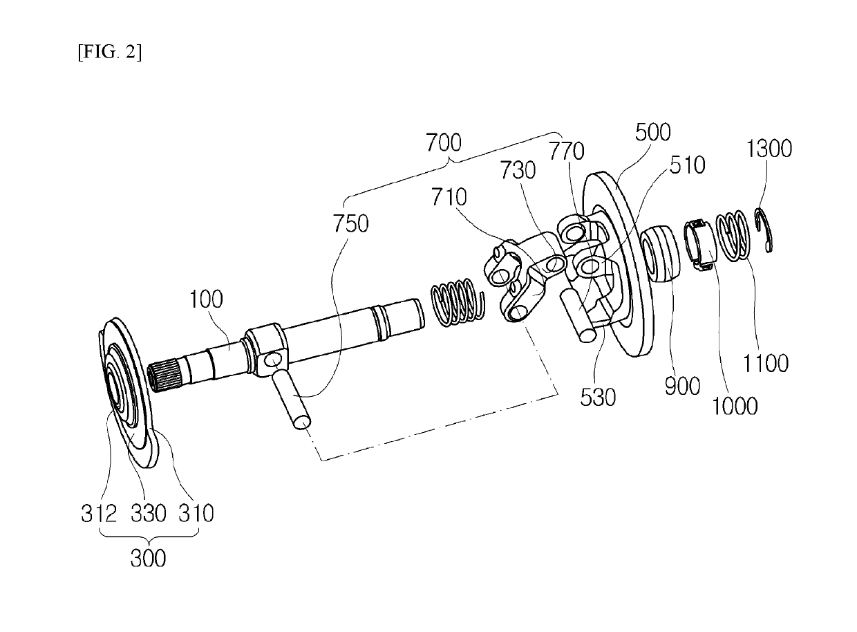
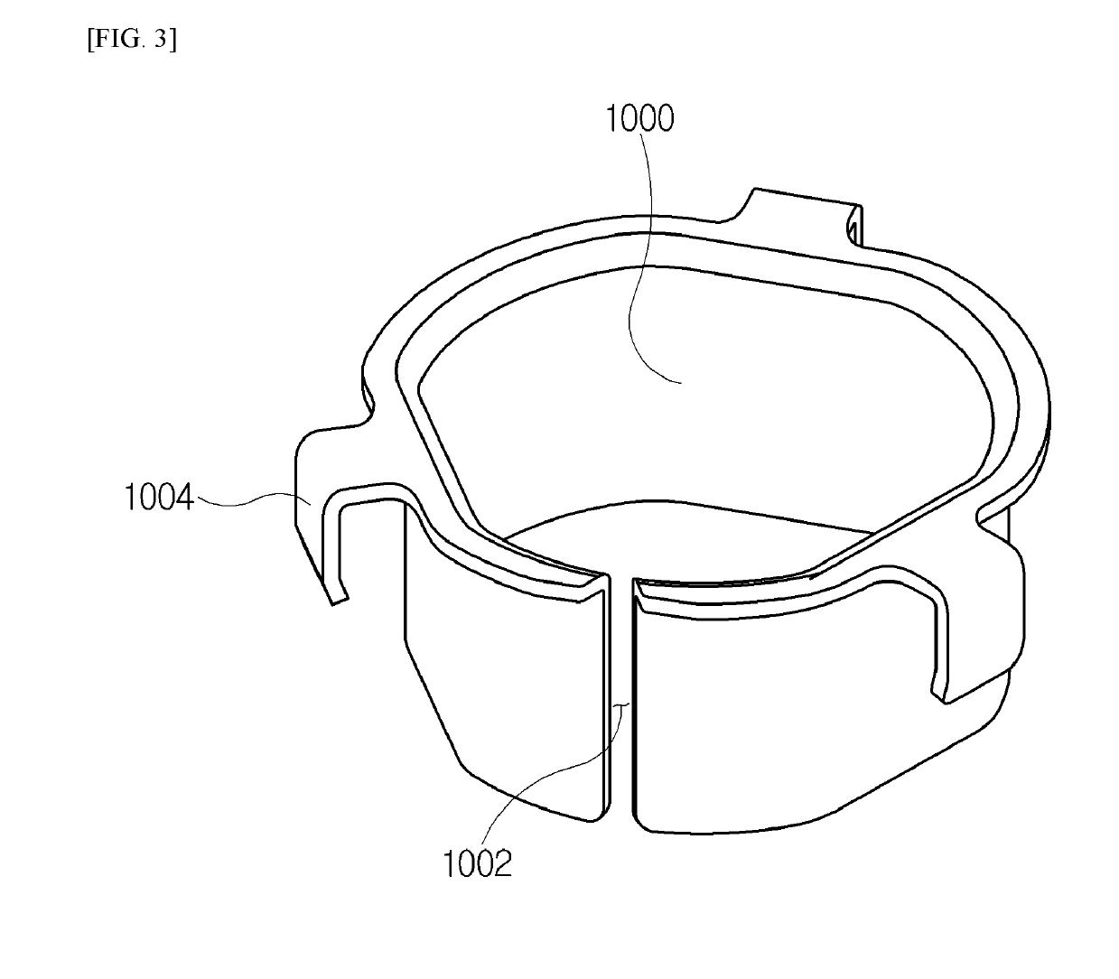
[0028]FIG. 1 is an assembled perspective view illustrating a drive unit for a variable capacity compressor at a maximum angle of inclination according to an embodiment of the present invention. FIG. 2 is an exploded perspective view illustrating the drive unit for a variable capacity compressor according to FIG. 1. FIG. 3 is a perspective view illustrating a friction ring of the drive unit for a variable capacity compressor according to FIG. 1.

[0029]As illustrated in FIGS. 1 and 2, the drive unit for a variable capacity compressor, which is designated by reference numeral 10, according to the embodiment of the present invention is inserted into a compressor consisting of a cylinder block and front and rear housings. The drive unit 10 includes a pulley (not shown) that is powered by an en...


PUM


Abstract

The drive unit has an effect of maintaining controllability and preventing a hunting problem caused under low flow conditions since it includes a friction ring module.

Description

TECHNICAL FIELD[0001]The present invention relates to a drive unit for a variable capacity compressor, and more particularly, to a drive unit for a variable capacity compressor, which has a simplified structure.BACKGROUND ART[0002]In general, a compressor applied to air conditioning systems sucks refrigerant gas having passed through an evaporator to compress the same to high temperature and high pressure, and then discharges the compressed refrigerant gas to a condenser. As this compressor, there are used various types of compressors such as a reciprocating compressor, a rotary compressor, a scroll compressor, and a swash plate compressor.[0003]The swash plate compressor includes a disc-shaped swash plate that is obliquely installed to a drive shaft rotated by power transmitted from an engine to be rotated by the drive shaft. In addition, the principle of the swash plate compressor is to suck or compress and discharge refrigerant gas by rectilinearly reciprocating a plurality of pi...

Claims


Application Information

Patent Timeline
IPC IPC(8): F04B27/08F04B27/18
CPCF04B27/0895F04B27/18F04B27/10F04B27/1072F04B39/0284F04B27/08F04B39/02
Inventor SONG, SE YOUNG
Owner HANON SYST
Why Eureka
Try Eureka