Two-way clutch assembly

a two-way clutch and assembly technology, applied in the field of two-way clutches, can solve the problems of increasing the size, cost and complexity of the clutch assembly, and the hydraulic components are too slow to be useful in many applications, so as to achieve high efficiency operation, no drag, and simple and compact

Active Publication Date: 2019-06-13
KEYSTONE POWDERED METAL
View PDF0 Cites 2 Cited by
  • Summary
  • Abstract
  • Description
  • Claims
  • Application Information

AI Technical Summary

Benefits of technology

[0012]This invention provides an improved two-way clutch which can operate in a neutral position with virtually no drag for high efficiency operation. It is also of a relatively simple and compact design which is capable of fitting into the envelope of conventional two-way clutches and which can be engaged or disengages in short activation times of 20 milliseconds or less. The two-way clutch of this invention is also highly durable, extremely reliable, and provides for a long trouble-free service life. It is also designed to revert to a free-wheeling state on failure to avoid catastrophic damage from occurring. The two-way clutch of this invention is also amenable to being produced at a relatively low cost as compared to conventional two-way clutches.

Problems solved by technology

Rocker and sprag type one-way clutch assemblies can increase the torque capacity for a given package size compared to those of a roller-type clutch, but they are generally limited in torque transmitting capacity by the magnitude of the contact or bearing stresses caused by contact of the rockers or sprags with the races.
Conventional two-way clutches typically employ a first / reverse clutch pack which increases the size, cost, and complexity of the clutch assembly.
Additionally, such two-way clutches typically utilize hydraulic components which are too slow to be useful in many applications.
Another drawback associated with conventional two-way clutches is that they cause some degree of drag and the inefficiency associated therewith.
In other words, conventional two-way clutches are not typically energy efficient.
Conventional two-way clutches also typically lock-up in the case of clutch failure which can lead to a catastrophic condition.

Method used


Image

  • Two-way clutch assembly
  • Two-way clutch assembly
  • Two-way clutch assembly

Examples


Embodiment Construction

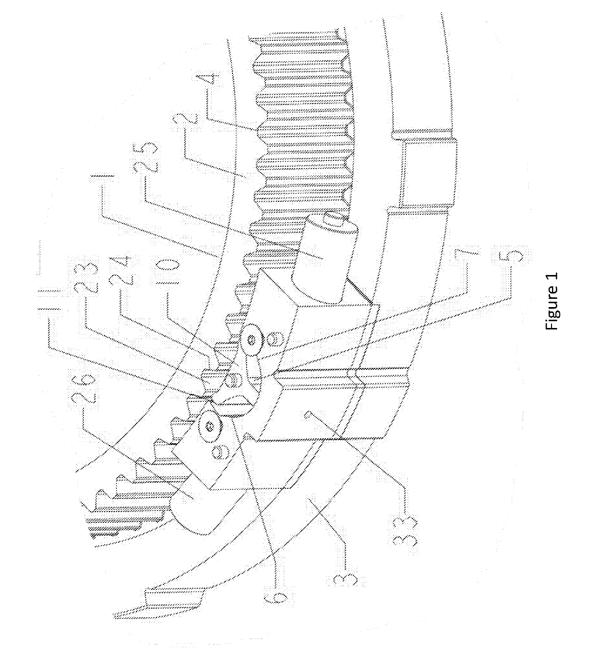
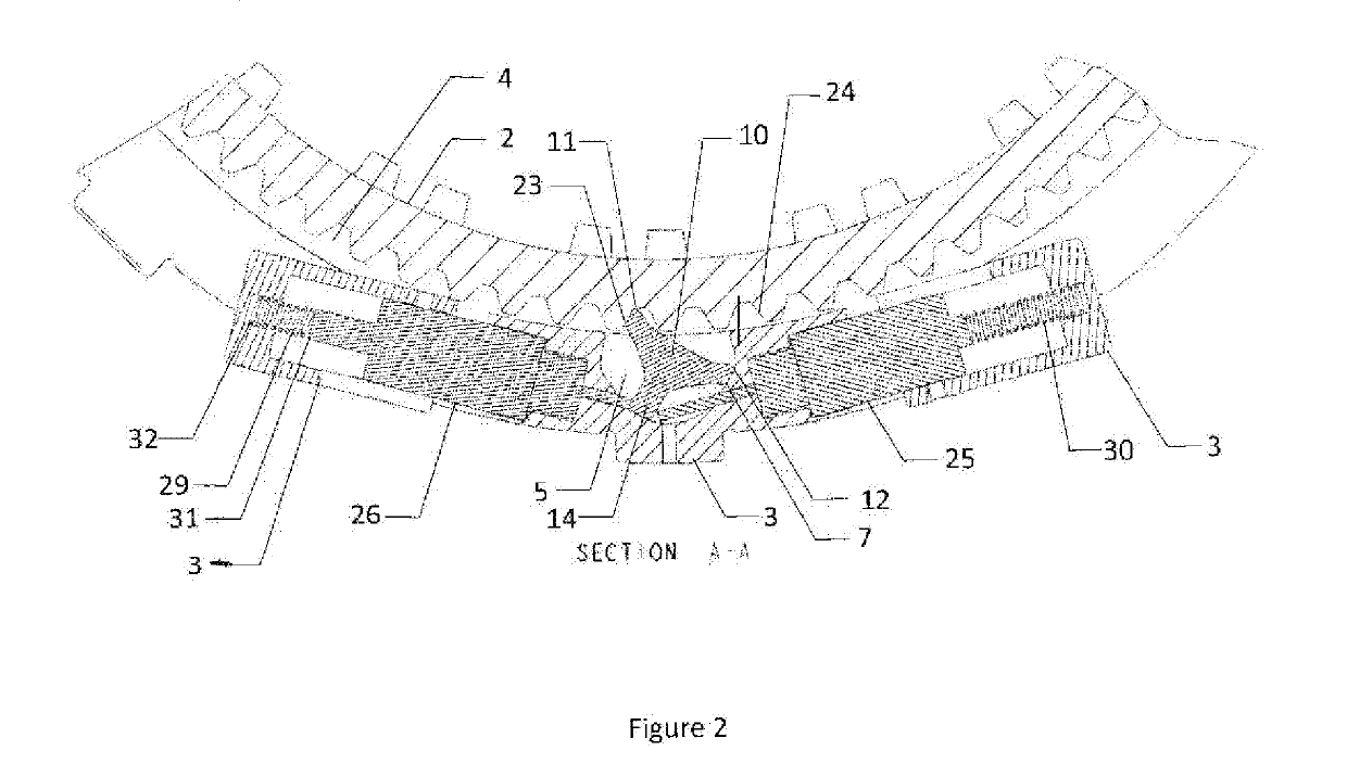
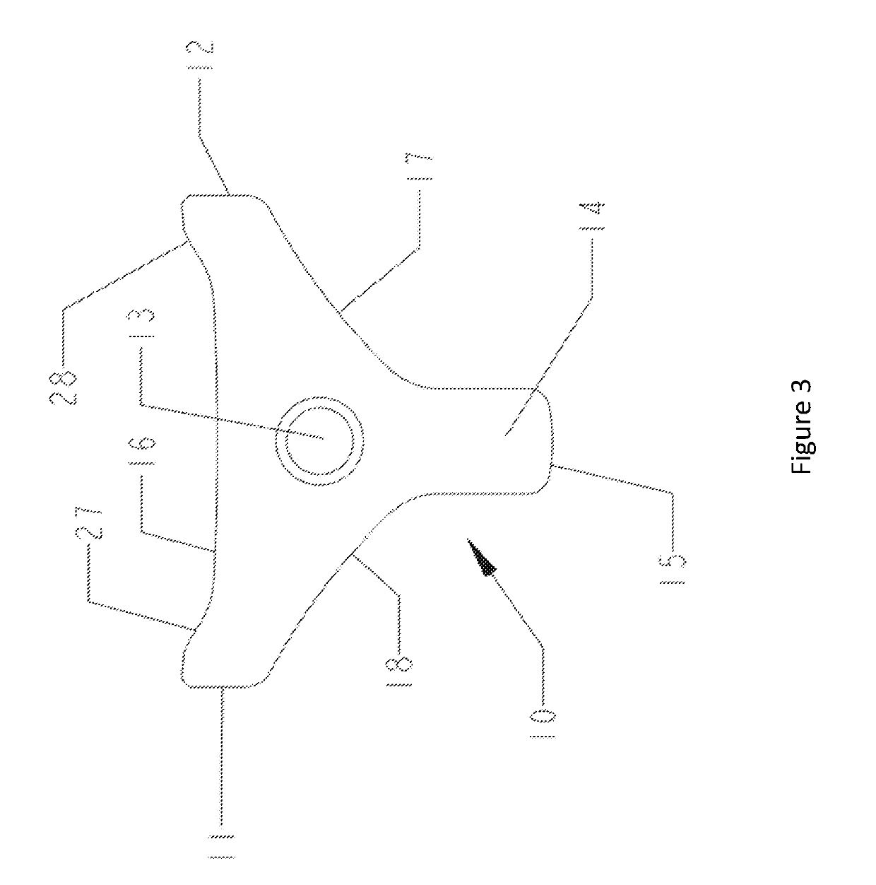
[0070]FIG. 1 illustrates a clutch assembly 1 which is comprised of (1) a cam plate 2 which includes cams 4 which are spaced about a central axis; (2) a rocker plate 3 which includes at least one pocket 5, wherein the pocket 5 includes a first rocker plate engagement surface 6 and a second rocker plate engagement surface 7; and (3) at least one rocker 10 which is pivotally situated within the pocket 5 of the rocker plate 3. The clutch assembly 1 illustrated in FIG. 1 is in a neutral position wherein the rocker 10 will not engage the cams 4 of the cam plate 2. However, the first solenoid 25 can be activated to push against the tail 14 of the rocker 10 so as to pivot the rocker 10 in a clockwise direction to bring the second rocker engagement face 11 which is complimentary to the second rocker plate engagement surface 22 into contact with the second rocker plate engagement surface 22. In doing so the first rocker engagement face 11 is pivoted to bring it into contact with the first cam...


PUM

PropertyMeasurementUnit
densityaaaaaaaaaa
densityaaaaaaaaaa
weight percentaaaaaaaaaa

Abstract

The present invention discloses a clutch assembly which is comprised of (1) a cam plate which includes cams which are spaced about a central axis; (2) a rocker plate which includes at least one pocket, wherein the pocket includes a first rocker plate engagement surface and a second rocker plate engagement surface; and (3) at least one rocker which is pivotally situated within the pocket of the rocker plate, (4) a first solenoid, and (5) a second solenoid, wherein the solenoids can be activated or deactivated to allow for the clutch to be in a neutral position (to allow for free rotation in both clockwise and counterclockwise directions), to prevent rotation in a clockwise direction while allowing for free rotation in a counterclockwise direction, or to prevent rotation in a counterclockwise direction while allowing for free rotation in a clockwise direction.

Description

[0001]This is a continuation-in-part application of U.S. patent application Ser. No. 14 / 669,405, filed on Mar. 26, 2015, which claims the benefit of U.S. Provisional Patent Application Ser. No. 61 / 971,944, filed on Mar. 28, 2014. The teachings of U.S. patent application Ser. No. 14 / 669,405 and U.S. Provisional Patent Application Ser. No. 61 / 971,944 are incorporated by reference herein in their entirety.FIELD OF THE INVENTION[0002]The invention relates to a two-way clutch that can optionally produce a drive connection between components when their relative rotation is in a first direction or a second direction (clockwise or counterclockwise), but which overruns when the relative rotation is in the opposite direction. The two-way clutch can also operate in a neutral position which does not produce a drive connection in either direction and while in the neutral position operates with virtually no drag. Additionally, the two-way clutches of this invention utilize one or more solenoids t...

Claims


Application Information

Patent Timeline
Patent Type & Authority Applications(United States)
IPC IPC(8): F16D41/16C22C38/22C22C38/12C22C38/08
CPCF16D41/16C22C38/22C22C38/12C22C38/08F16D11/16B22F5/00C22C33/0264B22F2998/10F16D41/14B22F3/02B22F3/10B22F3/24B22F2003/248
Inventor REITER, BRADLEYANDERSON, GARY L.
Owner KEYSTONE POWDERED METAL
Why Eureka
Try Eureka