
Method for producing a power electronics system

a technology of power electronics and electronics, applied in the direction of printed circuit aspects, dynamo-electric machines, stacked spaced pcbs, etc., can solve the problem that built-on accessories are not readily amenable to modular manufactur

Active Publication Date: 2019-06-13
SEMIKRON ELECTRONICS GMBH & CO KG
View PDF2 Cites 0 Cited by
  • Summary
  • Abstract
  • Description
  • Claims
  • Application Information

AI Technical Summary

Benefits of technology

The present invention provides a method for assembling a power electronics system that includes a cooling device, a switching device, a terminal device, a capacitor device, and a control device. This system can be easily produced using modular components. The method also includes a first mounting device with a second cutout, which creates a subarea on the substrate that is remote from the cooling device. This facilitates the assembly of the various components and ensures optimal performance of the power electronics system.

Problems solved by technology

Such built-on accessories are not readily amenable to modular manufacture, possibly with different configurations of the terminal elements given the same configuration of the switching device.

Method used


Image

  • Method for producing a power electronics system
  • Method for producing a power electronics system
  • Method for producing a power electronics system

Examples


Embodiment Construction

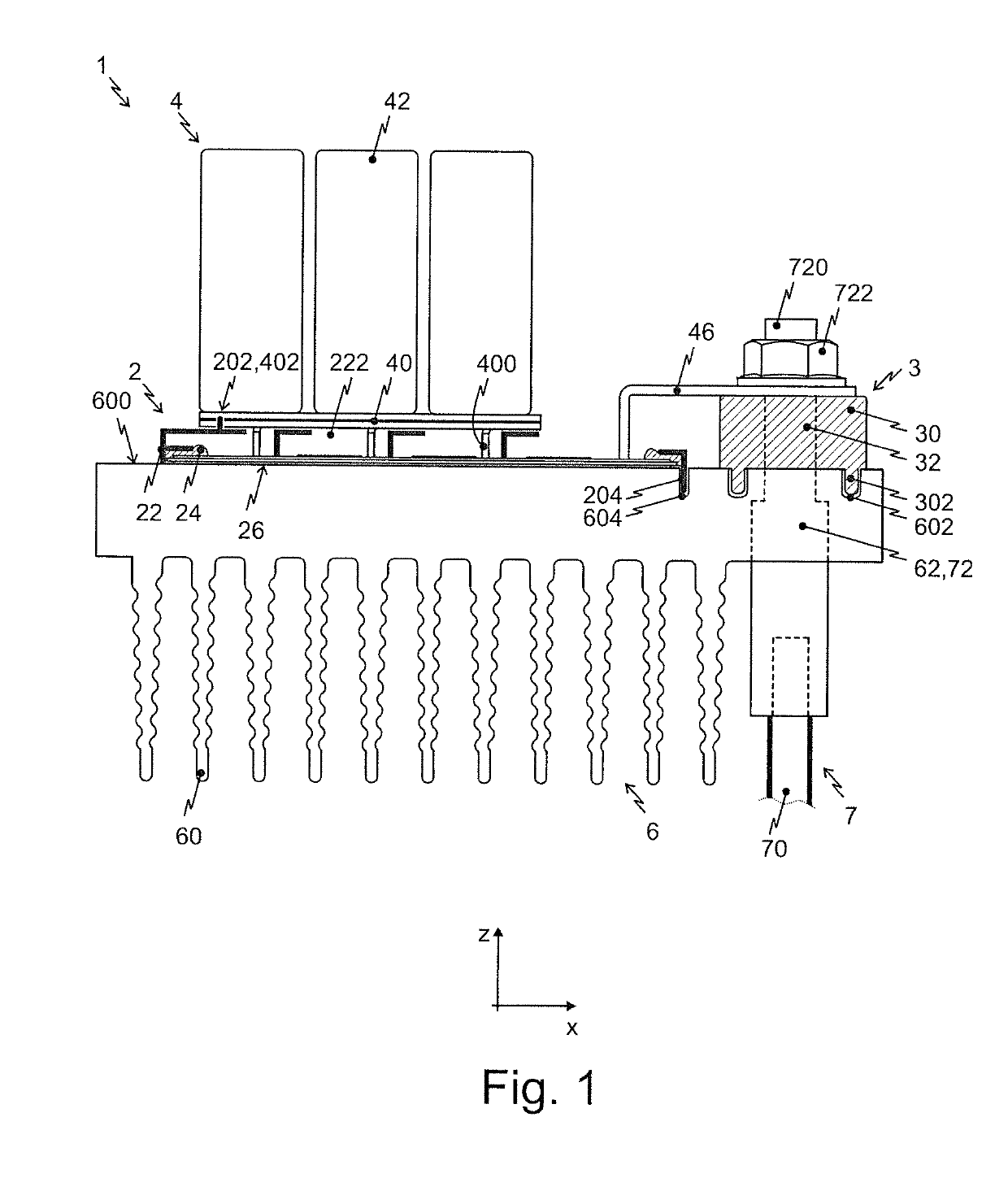
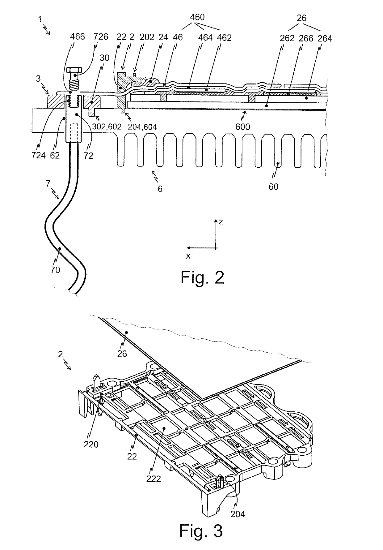
[0034]Reference will now be made in detail to embodiments of the invention. Wherever possible, same or similar reference numerals are used in the drawings and the description to refer to the same or like parts or steps. The drawings are in simplified form and are not to precise scale. The word ‘couple’ or ‘link’ or ‘connect’ and similar terms do not necessarily denote direct and immediate connections, but also include connections through intermediate elements or devices. For purposes of convenience and clarity only, directional (up / down, etc.) or motional (forward / back, etc.) terms may be used with respect to the drawings. These and similar directional terms should not be construed to limit the scope in any manner. It will also be understood that other embodiments may be utilized without departing from the scope of the present invention, and that the detailed description is not to be taken in a limiting sense, and that elements may be differently positioned, or otherwise noted as in...


PUM

PropertyMeasurementUnit
electrically insulatingaaaaaaaaaa
areaaaaaaaaaaa
inductanceaaaaaaaaaa

Abstract

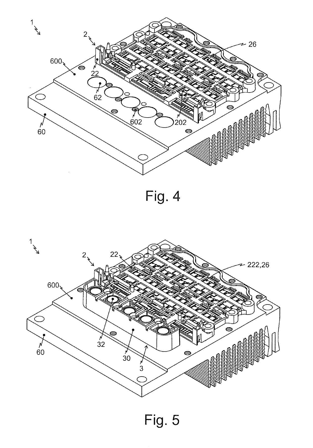
A method for producing a power electronics system having a cooling device, a switching device, a terminal device, a capacitor device and a control device includes the following production steps: providing a cooling device with a plurality of first and second positioning cutouts; providing the switching device with a substrate and a first mounting device, which has first positioning devices; providing the terminal device, which is completely independent of the switching device, i.e. forms a dedicated component part or a dedicated assembly, with a second mounting device, which has second positioning devices; arranging the switching device on the cooling device, wherein the first positioning devices are arranged in the respectively assigned first positioning cutouts; arranging the terminal device on the cooling device, wherein the respective second positioning devices are arranged in the assigned second positioning cutouts; arranging the capacitor device.

Description

CROSS REFERENCE TO RELATED APPLICATIONS[0001]This application relates to, and claims priority from, DE Ser. No.:10 2017 129 707.3 filed Dec. 13, 2017, the entire contents of which are incorporated herein by reference.FIGURE SELECTED FOR PUBLICATION[0002]FIG. 7.BACKGROUND OF THE INVENTIONField of the Invention[0003]The present invention relates to a method for producing a power electronics system having a cooling device, a switching device, a terminal device, a capacitor device and a control device. This power electronics system is preferably intended for application in fully or partially electrically operated vehicles, in particular also in industrial trucks such as fork-lift trucks.Description of the Related Art[0004]The related art includes a circuit arrangement having a basic body, having at least one substrate having an intermediate circuit board, having a pressure device and having a driver circuit is known from the general prior art, for example as disclosed in DE 101 27 947 A...

Claims


Application Information

Patent Timeline
Patent Type & Authority Applications(United States)
IPC IPC(8): H05K1/02H05K1/18H05K3/36H05K1/14H05K7/20H01R12/51
CPCH05K1/0203H05K1/181H05K3/368H05K1/144H05K7/209H05K7/20854H01R12/515H02K5/225H02K11/33H02K2211/03H05K2201/066H05K2201/10015H05K2201/10166H05K2201/10522H05K2201/1031H05K2201/042B62D65/02H05K1/0209H05K2203/167H05K3/0061Y10T29/49126
Inventor HUNKA, THOMASLEDERER, MARCOPOPP, RAINERWEISS, STEFANSTURM, PATRICK
Owner SEMIKRON ELECTRONICS GMBH & CO KG
Learn More