
Transapical removal device

a technology of a removal device and a stent, which is applied in the field of transapical removal devices, can solve the problems of swollen feet or ankles, shortness of breath and fatigue, heart murmur, etc., and achieves the effects of reducing the risk of pulmonary hypertension, and improving the effect of pulmonary hypertension

Pending Publication Date: 2019-06-20
EVALVE
View PDF3 Cites 14 Cited by
  • Summary
  • Abstract
  • Description
  • Claims
  • Application Information

AI Technical Summary

Benefits of technology

The patent describes a device and method for removing a mitral valve clip or heart tissue through a catheter procedure. The device includes a delivery catheter with a snare head that can be expanded to capture the clip or tissue for removal. The snare head has a controller to control its position and an ablation delivery catheter to remove the tissue. The device can also have a grasping tool for manipulating the clip or tissue. Additionally, the patent describes a deployment mechanism for replacing a removed mitral valve clip with a transcatheter valve. The technical effects of the invention include improved precision and minimized damage to the heart tissue during the removal procedure.

Problems solved by technology

Because blood cannot move through the heart or to the rest of the body as efficiently in people suffering from mitral valve regurgitation, symptoms include shortness of breath and fatigue, as well as heart murmur, heart palpitations, and swollen feet or ankles.
Unfortunately, after mitral valve clip deployment, the mitral valve clip can only be removed surgically, closing the door for future percutaneous mitral valve replacement and causing elevated morbidity and mortality.
Additionally, some patients with mitral valve regurgitation undergo transcatheter mitral valve replacement and subsequently experience a left ventricular outflow tract (LVOT) obstruction.

Method used


Image

  • Transapical removal device
  • Transapical removal device
  • Transapical removal device

Examples


Embodiment Construction

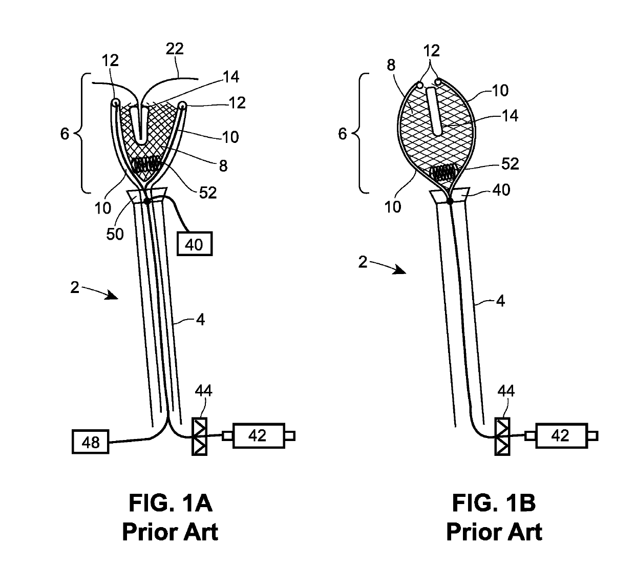
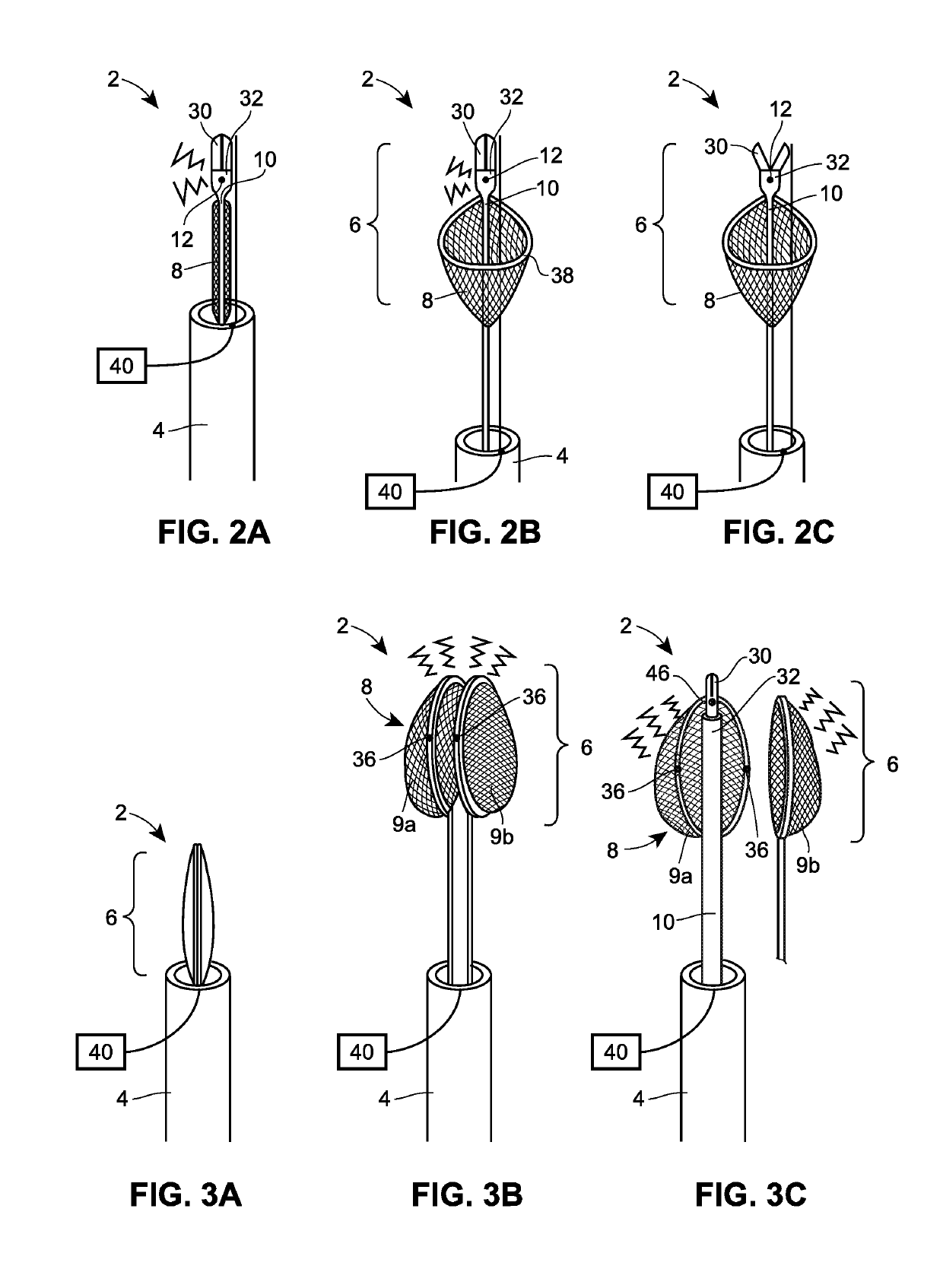
[0029]FIGS. 1A and 1B illustrate a first arrangement of a transapical removal device 2 of the present disclosure. The transapical removal device 2 includes a delivery catheter 4, a snare head 6, a snare basket 8, a spring 52, and ablation delivery catheters 10 with electrodes 12. An electrical source 42 and an ablation source 48 are in communication with the electrodes 12, and a switch 44 alternately permits and ceases to permit electrical current from the electrical source 42 to flow to the electrodes 12. In FIG. 1A, the snare head 6 and snare basket 8 are in a deployed state outside of the delivery catheter 4, and a mitral clip 14 is surrounded by the sides of the snare basket 8. The electrodes 12 of the ablation delivery catheters 10 are aligned with tissue of the heart that is to be ablated in order for the mitral clip 14 to be captured. For example, such tissue may be ablated when a control signal is provide to activate the ablation source 48 to provide an ablation signal, such...


PUM


Abstract

A transapical removal device that can be deployed in a catheter procedure to capture for removal or alteration a mitral valve clip or heart tissue, such as the anterior leaflet of the mitral valve, and methods of use are disclosed. The removal device includes a delivery catheter configured to be deployed near a mitral valve using a guide catheter. The delivery catheter has a snare head at the distal end, which assumes a collapsed state during movement of the delivery catheter through the guide catheter and deployed state for capturing a mitral valve clip or anterior leaflet. The snare head has one or more ablation delivery catheters configured to ablate tissue surrounding the pre-positioned mitral valve clip or anterior leaflet. In some arrangements within the scope of the present disclosure, the removal device includes a deployment mechanism for deploying a new transcatheter valve into the mitral valve.

Description

CROSS-REFERENCE TO RELATED APPLICATION[0001]The priority benefit of U.S. Provisional Patent Application No. 62 / 352,235, filed Jun. 20, 2016, and entitled “Transapical Removal Device” is claimed and the entire contents thereof are incorporated by reference herein.FIELD OF THE DISCLOSURE[0002]This disclosure relates generally to a transapical removal device, and more specifically, to a transapcial removal device for removal of a mitral valve clip or the anterior leaflet of the mitral valve.BACKGROUND[0003]Mitral valve regurgitation occurs when a heart's mitral valve does not close tightly, allowing some blood to leak backward through the mitral valve into the atrium rather than flowing through the aortic valve. Mitral valve regurgitation is present in approximately 1.7% of the adult population, and the incidence rises with advancing age such that more than 9% of adults 75 years of age and older have moderate or severe mitral valve regurgitation. Because blood cannot move through the h...

Claims


Application Information

Patent Timeline
Patent Type & Authority Applications(United States)
IPC IPC(8): A61B18/14A61B17/128A61B18/24A61B17/22A61B18/02A61B17/34A61B17/50A61B17/221
CPCA61B18/1492A61B17/1285A61B18/24A61B17/22031A61B18/02A61B18/1445A61B17/34A61B17/50A61B17/221A61B2018/1226A61B2018/00267A61B2018/00273A61B2017/22097A61B2017/22035A61B2017/2215A61B2017/00876A61B2017/00243A61B2017/00318A61B2017/00358A61B2018/0212A61B2018/00577A61B2018/00369A61B17/22A61B17/32
Inventor DE MARCHENA, M.D, EDUARDO
Owner EVALVE
Learn More