Aspirator system

a technology of aspirator and aspirator body, which is applied in the direction of machines/engines, transportation and packaging, aircraft ejection means, etc., can solve the problem of reducing the efficiency of aspirator

Inactive Publication Date: 2019-06-20
THE BF GOODRICH CO
View PDF2 Cites 6 Cited by
  • Summary
  • Abstract
  • Description
  • Claims
  • Application Information

AI Technical Summary

Benefits of technology

[0005]In addition to one or more of the features described herein, the plurality of nozzles are spaced apart from the central longitudinal axis such that a central flow path is disposed about the central longitudinal axis and is free of blockage from any portion of the plurality of nozzles.

Problems solved by technology

Blockage within the flow path of the aspirator may reduce the efficiency of the aspirator.

Method used


Image

  • Aspirator system
  • Aspirator system

Examples


Embodiment Construction

[0013]A detailed description of one or more embodiments of the disclosed apparatus and method are presented herein by way of exemplification and not limitation with reference to the Figures.

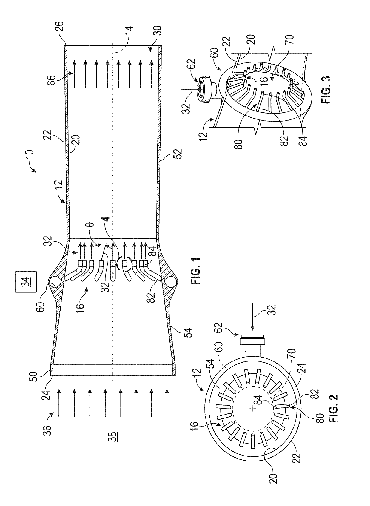
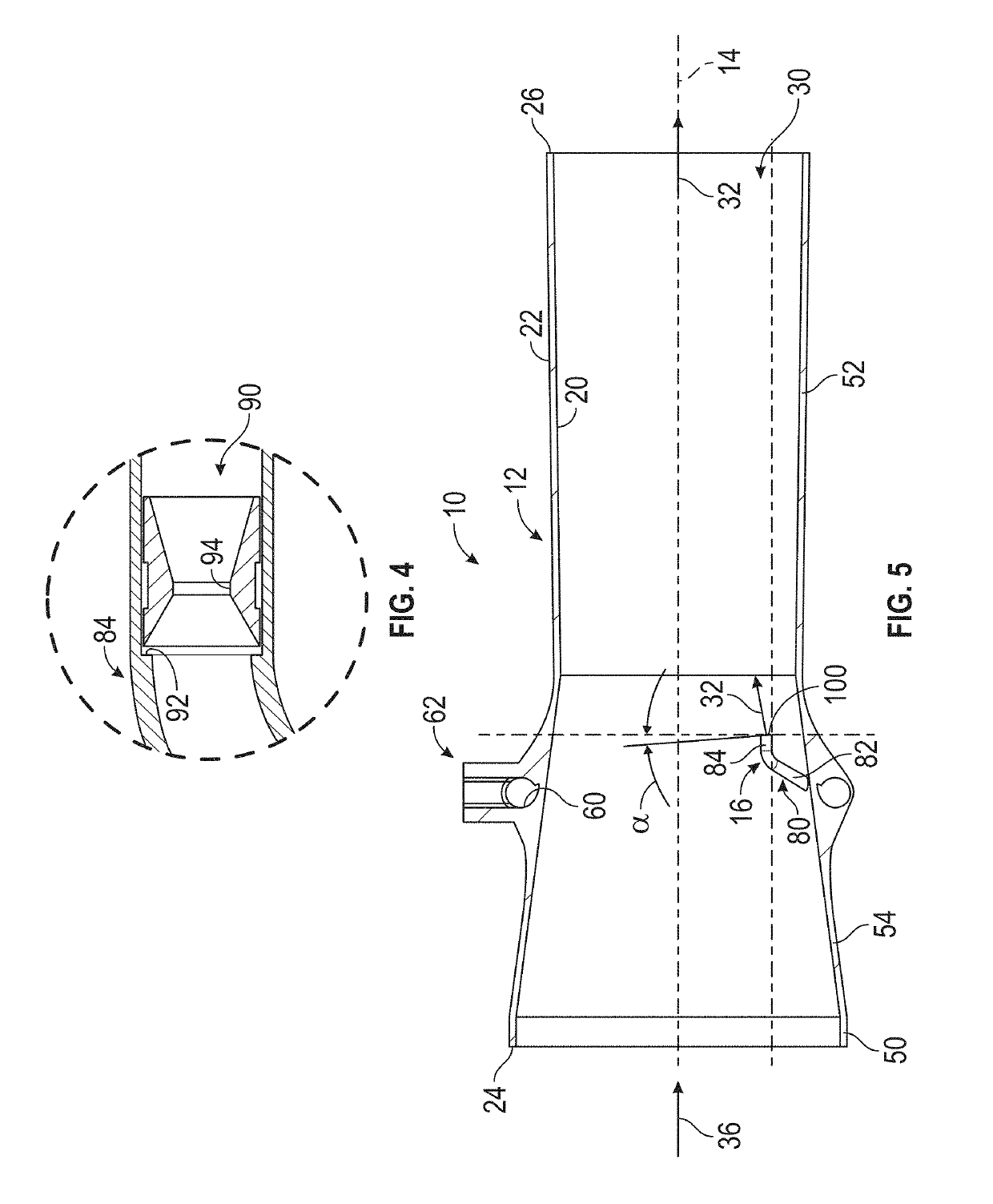
[0014]Referring to FIGS. 1 and 5, an aspirator system 10 is illustrated. The aspirator system 10 includes an aspirator body 12 that extends along a longitudinal axis 14 and a plurality of nozzles 16. The longitudinal axis 14 may be a central longitudinal axis about which the aspirator body 12 and the plurality of nozzles 16 are disposed.

[0015]The aspirator body 12 includes an inner surface 20 and an outer surface 22 that each extend between a first end 24 and a second end 26 along the longitudinal axis 14. The inner surface 20 of the aspirator body 12 defines a fluid channel 30 that receives a first fluid flow 32 from a first fluid source 34 and receives / entrains / induces a second fluid flow 36 from a second fluid source 38. The first fluid flow 32 and the second fluid flow 36 are mixed within the...


PUM


Abstract

An aspirator system for inflating an inflatable device includes an aspirator body and a plurality of nozzles. The aspirator body has an inner surface and an outer surface that each extend between a first end and a second end along a central longitudinal axis. The aspirator body defines a distribution channel that is disposed between the inner surface and the outer surface. The plurality of nozzles are fluidly connected to the distribution channel and extend inwardly from the inner surface towards but are spaced apart from the central longitudinal axis.

Description

CROSS-REFERENCE TO RELATED APPLICATIONS[0001]This patent application claims priority to Indian Provisional Patent Application Serial No. 201711045610, filed Dec. 19, 2017, which is incorporated herein by reference in its entirety.BACKGROUND[0002]Exemplary embodiments pertain to the art of aspirators.[0003]Aspirators are used to entrain ambient air into an inflatable structure during inflation. A high velocity primary gas may be ejected through nozzles of the aspirator and the high velocity primary gas is directed into the inflatable structure leading to a pressure differential which entrains ambient air into the inflatable structure. Blockage within the flow path of the aspirator may reduce the efficiency of the aspirator. There is a need in the industry for a device that has a reduced blockage area that results in higher efficiency through a higher secondary flow.BRIEF DESCRIPTION[0004]Disclosed is an aspirator system for inflating an inflatable device. The aspirator system include...

Claims


Application Information

Patent Timeline
Patent Type & Authority Applications(United States)
IPC IPC(8): F04F5/46B60C29/00B64D25/14F04F5/16
CPCF04F5/467B63C9/24B64D25/14F04F5/16F04F5/461B63C2009/0023F04F5/48F04F5/466
Inventor WERBELOW, JEFF M.THAMMANNA, JAGADISHSOMASUNDARAM, KRISHNA PREETHAMDATTATRI, SHYAMKUMAR
Owner THE BF GOODRICH CO
Why Eureka
Try Eureka