Solar cell module

a solar cell module and solar cell technology, applied in the field can solve the problems of excessive bending rigidity of solar cell modules and considerable deflection of elements, and achieve the effects of plate thickness, and reducing the weight of solar cell modules

Active Publication Date: 2019-06-20
TOYOTA JIDOSHA KK +1
View PDF3 Cites 0 Cited by
  • Summary
  • Abstract
  • Description
  • Claims
  • Application Information

AI Technical Summary

Benefits of technology

[0018]In this solar cell module, the plate thickness of the sealing layer is uniform in the vehicle front-rear direction. Accordingly, even if the plate thickness of the solar cell module is reduced in conjunction with the increase of the curvature in the vehicle front-rear direction of the solar cell module, the plate thickness of the sealing layer is not reduced. In other words, compared with a structure in which the plate thickness in the vehicle front-rear direction of the solar cell module is uniform, while the plate thickness is reduced in conjunction with the increase of the curvature and the weight of the solar cell module is reduced, the plate thickness of the sealing layer can...

Problems solved by technology

In other words, the bending rigidity of the solar cell module is actually excessive in locations where the curvature is relatively large, and there is room for improvement from the standpoint of weight reduction.
Typically, an impact load is...

Method used


Image

  • Solar cell module
  • Solar cell module
  • Solar cell module

Examples


first embodiment

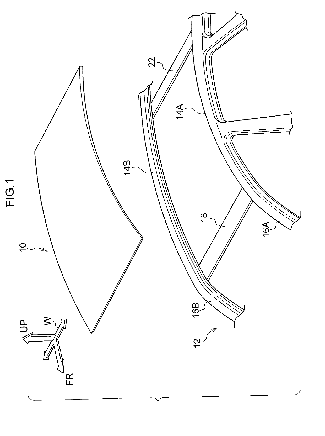
[0038]A solar cell module according to a first exemplary embodiment of the present disclosure will now be described with reference to FIG. 1 through FIG. 4D. Note that the solar cell module according to the present exemplary embodiment is mounted as a vehicle roof on a vehicle frame component. Moreover, each drawing is a typical view, and structure that has little or no relation to the present exemplary embodiment has been omitted from the drawings. Furthermore, an arrow FR, an arrow W, and an arrow UP that are shown in the drawings respectively indicate a vehicle forward direction, a vehicle width direction, and a vehicle upward direction.

[0039](Structure)

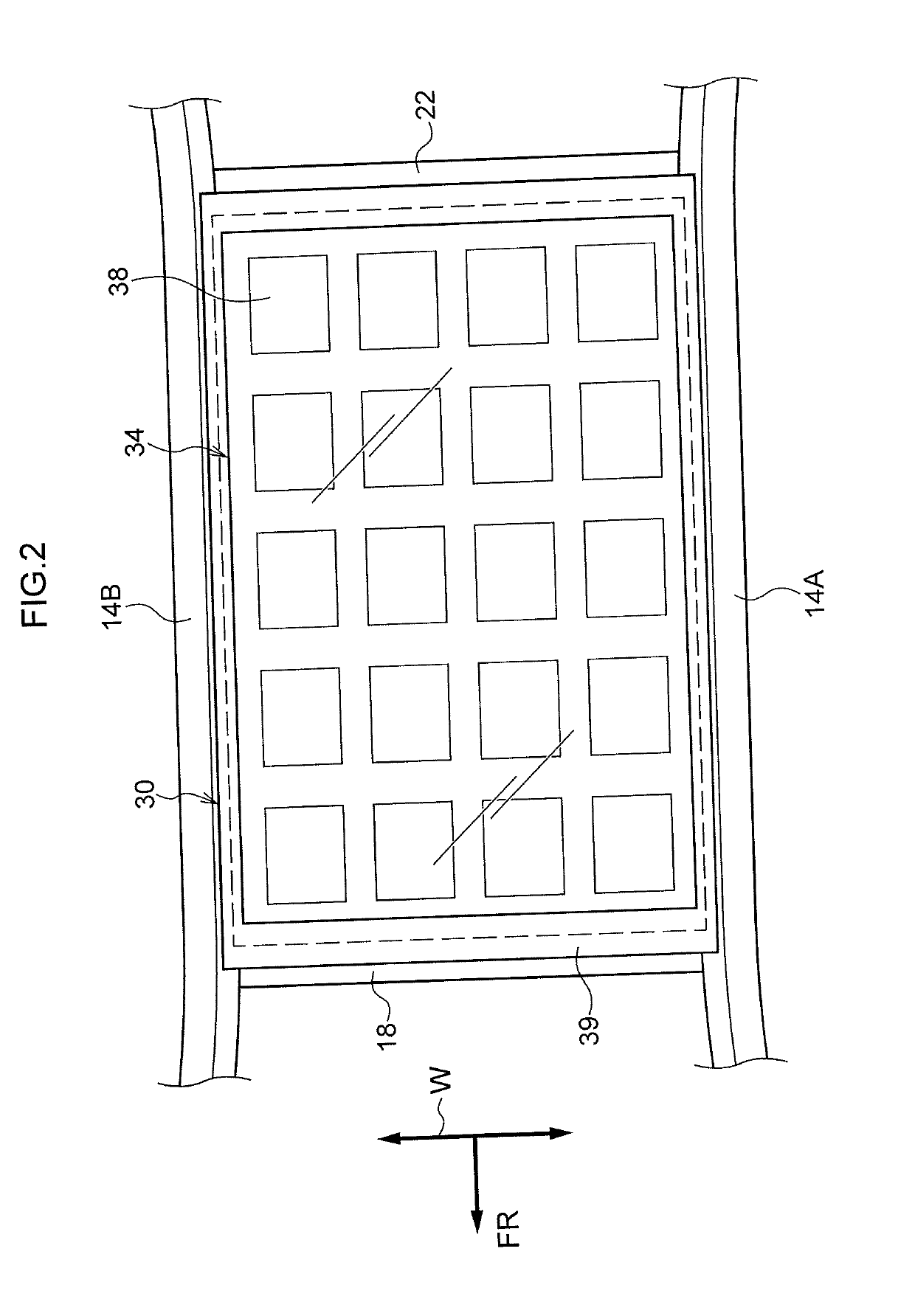
[0040]As is shown in FIG. 1, a vehicle solar call module 10 according to the present exemplary embodiment is mounted as a roof on a vehicle body 12. A pair of roof side rails 14A and 14B are provided extending in the vehicle front-rear direction at both end portions in the vehicle width direction of the vehicle body 12 as componen...

second embodiment

[0062]A solar cell module according to a second exemplary embodiment of the present disclosure will now be described with reference to FIG. 5. Note that component elements that are the same as in the first exemplary embodiment are given the same reference symbols and a detailed description thereof is omitted. Furthermore, as the second exemplary embodiment differs from the first exemplary embodiment only in the configuration of the front surface layer 30 and the rear surface layer 36, only these portions are described below.

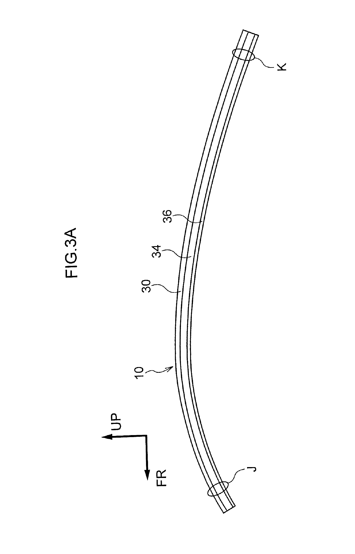
[0063]In a solar cell module 50, the plate thickness of the front surface layer 30 is formed proportionately thinner in portions where the curvature in the vehicle front-rear direction is larger. In contrast, the sealing layer 34 and the rear surface layer 36 are formed having uniform plate thicknesses in the vehicle front-rear direction.

[0064]In other words, an adjustment is made to the plate thickness of just the front surface layer 30 such that the plate thick...

third embodiment

[0066]A solar cell module according to a third exemplary embodiment of the present disclosure will now be described with reference to FIG. 6. Note that component elements that are the same as in the first exemplary embodiment are given the same reference symbols and a detailed description thereof is omitted. Furthermore, as the third exemplary embodiment differs from the first exemplary embodiment only in the configuration of the front surface layer 30 and the rear surface layer 36, only these portions are described below.

[0067](Structure)

[0068]In a solar cell module 60, the plate thickness of the rear surface layer 36 is formed proportionately thinner in portions where the curvature in the vehicle front-rear direction is larger. In contrast, the front surface layer 30 and the sealing layer 34 are formed having uniform plate thicknesses in the vehicle front-rear direction.

[0069]In other words, an adjustment is made via the plate thickness of just the rear surface layer 36 such that ...


PUM

PropertyMeasurementUnit
Thicknessaaaaaaaaaa
Stiffnessaaaaaaaaaa

Abstract

A solar cell module having curvature in a vehicle front-rear direction which varies from a vehicle front side towards a vehicle rear side, the solar cell module includes: a sealing layer formed from resin and in which power generating elements are sealed; a front surface layer formed from resin and joined to a light-receiving surface side of the power generating elements in the sealing layer; and a rear surface layer formed from resin and joined to an opposite side from the light-receiving surface side of the power generating elements in the sealing layer, wherein a plate thickness of portions where the front surface layer, the sealing layer, and the rear surface layer are laminated together is formed so as to become proportionately thinner as the curvature in the vehicle front-rear direction increases.

Description

CROSS-REFERENCE TO RELATED APPLICATION[0001]This application claims priority under 35 USC 119 from Japanese Patent Application No. 2017-244451 filed on Dec. 20, 2017, the disclosure of which is incorporated by reference herein in its entirety.BACKGROUNDTechnical Field[0002]The present disclosure relates to a solar cell module.Related Art[0003]Conventionally, as described in Japanese Unexamined Patent Application (JP-A) No. 2015-023070, a solar cell module is used in which a sealing layer that seals solar cells is sandwiched between a front surface layer, which is positioned on a light-receiving surface side of the solar cells, and a rear surface layer, which is positioned on the opposite side from the light-receiving surface. When a solar cell module is used as the roof of a vehicle, the front surface layer and the like are formed from resin in order to reduce weight. Additionally, the thicknesses of the front surface layer, the sealing layer, and the rear surface layer are formed s...

Claims


Application Information

Patent Timeline
IPC IPC(8): H01L31/048B32B3/26B32B27/08
CPCH01L31/048B32B3/263B32B27/08H02S99/00B32B2250/03B32B2457/12B62D25/06B60R16/03H02S20/30B32B2250/24B32B27/365B32B1/00B32B2307/732B32B3/08B32B2605/00B32B2307/546B32B27/306B32B2307/412
Inventor SAKABE, MOTOYAOGATA, KAZUYOSHIINABA, HIROTAKA
Owner TOYOTA JIDOSHA KK
Why Eureka
Try Eureka