
Knitted component

a technology of knitted components and components, applied in the field of knitted components, can solve the problems of increasing the cost of the resulting articles of footwear or apparel, limiting the number of different types of yarn that can be used, and reducing the flexibility and support of knitted components, so as to achieve the right level of flexibility and support, prevent injuries during exercise, and bend easily

Active Publication Date: 2019-06-27
ADIDAS
View PDF16 Cites 0 Cited by
  • Summary
  • Abstract
  • Description
  • Claims
  • Application Information

AI Technical Summary

Benefits of technology

This patent describes a method for making a knitted component for a shoe or footwear. By using a second linear loop density in the second portion of the knitted layer, the second portion is made stiffer and stronger than the first portion. This allows for the shoe or footwear to have the right amount of strength and flexibility in different areas. Additionally, a sole is attached to the upper to provide stability and protection for the foot. Overall, this invention results in a lightweight, flexible, and comfortable shoe or footwear that provides adequate support and flexibility where needed.

Problems solved by technology

However, it is a disadvantage of existing knitting techniques, that engineering certain properties, such as stretchability or elasticity, to vary across different portions of a knitted component is a complex and time consuming task.
However, it can take hours for a single knitted component with complex knitting patterns to be knitted, even on modern knitting machines, which increases the cost of the resulting articles of footwear or apparel.
However, the number of yarn carriers limits the number of different types of yarn that can be used.
The complexity and thus the time required for the knitting process is also increased by using several types of yarn.
However, there are several disadvantages of this way of engineering the properties of a knitted fabric.
Firstly, the coating operation is a separate process step that requires additional time and resources, e.g. for applying and for then curing the polymer.
Secondly, the breathability of such a knitted component is poor, because of the polymer coating.
Moreover, the coating is detrimental to the feel of the surface of the knitted component and thus the wearing comfort.
However, these methods to modify stitch lengths during knitting have not been applied for the production of apparel or in footwear.
A key problem is that a differential in the knitting stitch length, or stitch height, is not stable and thus the differential is not maintained in a knitted fabric.
Instead, during further processing of the knitted fabric or when such an article of apparel or footwear is worn, the differential in stitch length is lost.
Thus, it is not possible with present methods, to produce a knitted component with locally varying properties by varying the stitch length.

Method used


Image

  • Knitted component
  • Knitted component
  • Knitted component

Examples


Embodiment Construction

[0086]In the following only some exemplary embodiments of the invention are described in detail. The person skilled in the art should be aware that these exemplary embodiments can be modified in a number of ways and combined with each other whenever compatible and that certain features may be omitted in so far as they appear dispensable.

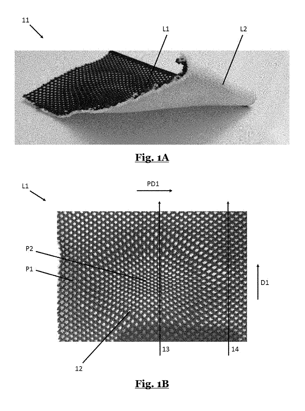
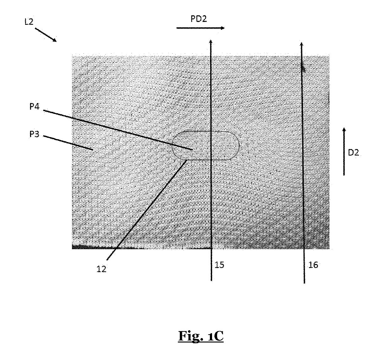
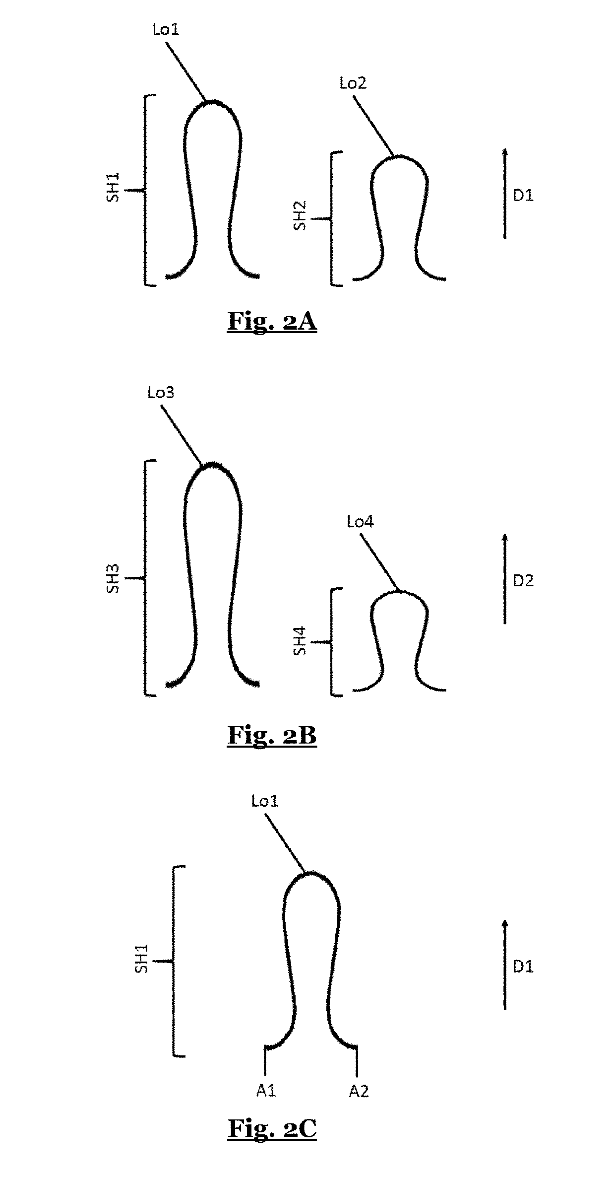
[0087]FIGS. 1A-C show an exemplary knitted component 11 according to the invention. The knitted component 11 comprises: (a) a first knitted layer L1 (shown in FIG. 1A and FIG. 1B), comprising a knitted first portion P1 with a first linear loop density along a first direction D1, a knitted second portion P2 with a second linear loop density along the first direction D1, wherein the second linear loop density is greater than the first linear loop density; (b) a second knitted layer L2 (shown in FIG. 1A and FIG. 1C), comprising a knitted third portion P3 with a third linear loop density along a second direction D2, a knitted fourth portion P4 with a fou...


PUM

PropertyMeasurementUnit
angleaaaaaaaaaa
angleaaaaaaaaaa
melting temperatureaaaaaaaaaa

Abstract

The present invention concerns a knitted component, especially for an article of apparel or footwear, including: a first knitted layer, including a knitted first portion with a first linear loop density along a first direction, a knitted second portion with a second linear loop density along the first direction, wherein the second linear loop density is greater than the first linear loop density; a second knitted layer, including a knitted third portion with a third linear loop density along a second direction, a knitted fourth portion with a fourth linear loop density along the second direction; wherein the first knitted layer is connected to the second knitted layer.

Description

TECHNICAL FIELD[0001]The present invention relates to a knitted component with engineered stiffness and elasticity, especially for use in apparel or footwear, and methods for producing the same.PRIOR ART[0002]Knitted components are popular in many types of apparel or footwear. Knitted fabric tends to be lightweight and stretchable and therefore lends itself to many uses. Apparel or footwear made from knitted components is comfortable and lightweight. Knitting enables a number of ways of engineering the properties of the knitted fabric. The two basic types of knitting: weft knitting and warp knitting enable different structural motives to be realized. Different knitting patterns can be knitted with different structural stability, stretchability or elasticity, and weight per unit area.[0003]Different portions of a fabric are subject to different requirements. For example, in a shoe upper certain regions, such as a toe region, a heel region, or a metatarsal region, require more support...

Claims


Application Information

Patent Timeline
Patent Type & Authority Applications(United States)
IPC IPC(8): A43B23/02D04B1/24A43B7/06A43B11/00A43B5/06
CPCA43B23/025D04B1/24A43B7/06A43B23/0275A43B23/027A43B11/00A43B5/06A43B23/024D10B2501/043D04B1/12D04B1/16D04B1/18A43B1/04D04B1/102D10B2403/023D04B1/246D10B2401/041D10B2331/04D04B1/104
Inventor HYMAS, JESSICA DOROTHY JANINEBRAUN, MICHAELPENG, YU JU
Owner ADIDAS
Learn More