Wind turbine, bearing housing and method for operating a wind turbine

a technology for wind turbines and bearings, applied in the direction of bearing repair/replacement, bearing unit rigid support, final product manufacturing, etc., can solve the problems of reducing maintenance and service costs, removing or re-using main bearings, and a large number of main bearings. the effect of failure or damage can be reduced, time and cost-intensiv

Inactive Publication Date: 2019-06-27
SIEMENS GAMESA RENEWABLE ENERGY AS
View PDF0 Cites 2 Cited by
  • Summary
  • Abstract
  • Description
  • Claims
  • Application Information

AI Technical Summary

Benefits of technology

[0008]The embodiment is based on the consideration to have a primary bearing setup and a secondary bearing setup in each bearing group. Advantageously the rotor shaft is therefore either rotatably arranged by the primary bearing setup or the secondary bearing setup of each bearing group. If the primary bearing setup is used to pivot the rotor shaft and a failure or damage occurs to the primary bearing setup or one of the primary bearing setups, the wind turbine can be stopped and the secondary bearing setups can be used to pivot the rotor shaft. Therefore there is no need to wait until the maintenance or service fleet is mobilized and the primary bearing setup is exchanged or repaired, as the secondary bearing setup can be used to pivot the rotor shaft or arrange the rotor shaft rotatably, respectively, and the wind turbine is made operational at least for the time the maintenance or service fleet needs to maintain or repair the primary bearing setups. As a matter of fact, the downtime of the wind turbine in case of failure or damage can be reduced since there are secondary bearing setups provided that can take over the function of the primary bearing setups. Advantageously it is less extensive to use the secondary bearing setups than to have the whole bearing housing exchanged. To change the bearing setups, it is for example merely necessary to change the bearing means from the primary bearing setup, that is damaged or needs maintenance to the corresponding secondary bearing setup. Therefore, the time and effort to change the bearing means or bearing between the bearing setups is much less than to have the bearing setup or even the whole bearing housing exchanged.
[0009]It is also possible, if the primary bearing setups are irreparably damaged, for example in the case of a raceway damage in the rotor shaft, to use the secondary bearing setups as a “second life” for the bearing of the wind turbine, as the bearing means can be used in the secondary bearing setups and therefore the bearing of the wind turbine does not have to be exchanged which is, as described before, a time and cost intensive undertaking.
[0010]The first bearing group and the second bearing group are arranged in axially spaced locations. Therefore, the rotor shaft is rotatably arranged or pivoted at two different locations that are axially spaced. Of course, the rotor shaft is rotatably arranged by either the primary bearing setups or the secondary bearing setups of the first bearing group and the second bearing group. Besides that, it is also possible to have only the primary bearing setup of the first bearing group changed to the secondary bearing setup if only the primary bearing setup of the first bearing group is damaged or needs maintenance. Thus, the primary bearing setup of the second bearing group can be kept in operation as there is no damage or need for maintenance or repair of the primary bearing setup of the second bearing group.

Problems solved by technology

As the size of wind turbines keeps growing to above 10 MW it is a problem to keep down the maintenance and service costs during the lifetime.
Especially the main bearing of such large wind turbines is a very expensive part to maintain and exchange, in particular on offshore wind turbines normally the whole bearing housing structure has to be exchanged.
Furthermore it is challenging to remove or exchange a main bearing as they are usually built in one piece, so that dismantling of the construction is required.

Method used


Image

  • Wind turbine, bearing housing and method for operating a wind turbine
  • Wind turbine, bearing housing and method for operating a wind turbine
  • Wind turbine, bearing housing and method for operating a wind turbine

Examples


Embodiment Construction

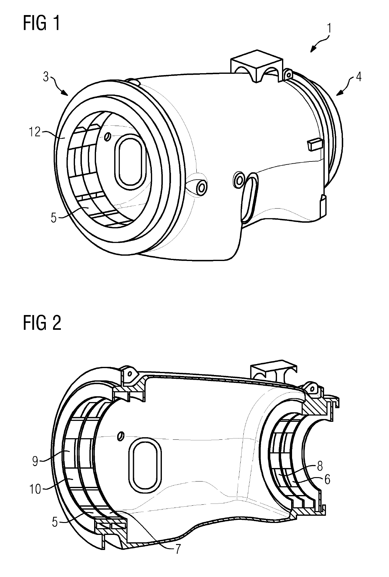
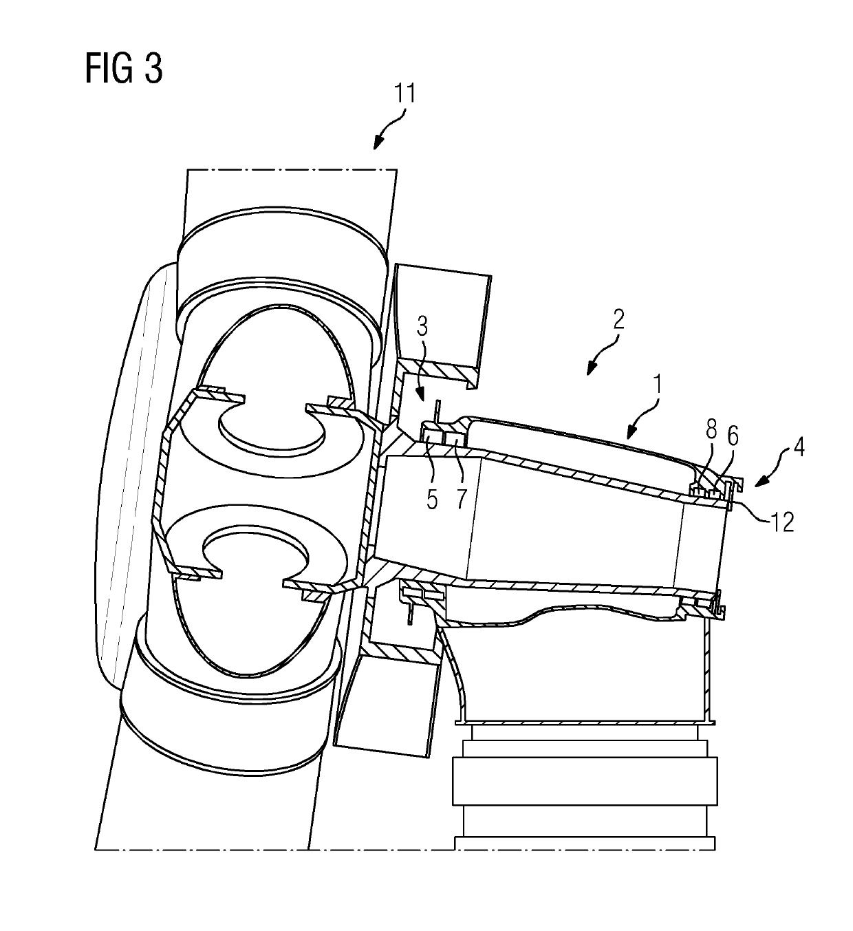
[0043]FIG. 1 shows a perspective view of a bearing housing 1 for a wind turbine 2, which is depicted in FIG. 3. The bearing housing 1 comprises a first bearing group 3 and a second bearing group 4, being axially spaced. The first bearing group 3 and the second bearing group 4 each comprise a primary bearing setup 5, 6 and secondary bearing setup 7, 8.

[0044]As can best be seen in FIG. 2, the primary bearing setup 5 and the secondary bearing setup 7 as well as the primary bearing setup 6 and the secondary bearing setup 8 abut each other axially. Therefore the pivot points for the rotor shaft (not shown) are similar independent of the use of the primary bearing setups 5, 7 or the secondary bearing setups 6, 8.

[0045]The bearing setups 5, 6, 7, 8 comprise notches 9 that are circumferentially arranged and able to receive bearing means or bearing, for example a fluid bearing. In case of sliding bearings exchangeable pads 10 can be received in the notches 9 and can be exchanged in case of p...


PUM


Abstract

Provided is a wind turbine, including a rotor with a rotor shaft connected to a generator and a bearing housing, whereby the bearing housing includes at least a first bearing group and a second bearing group each comprising at least a primary bearing setup and a secondary bearing setup in which bearing is receivable, whereby the rotor shaft is rotatably arranged by the primary bearing setups or the secondary bearing setups.

Description

CROSS-REFERENCE TO RELATED APPLICATIONS[0001]This application claims priority to PCT Application No. PCT / EP2017 / 065753, having a filing date of Jun. 27, 2017, based on EP Application No. 16182605.2, having a filing date of Aug. 3, 2016, the entire contents both of which are hereby incorporated by reference.FIELD OF TECHNOLOGY[0002]The following relates to a wind turbine, comprising a rotor with a rotor shaft connected to a generator and a bearing housing.BACKGROUND[0003]In conventional wind turbines, as known from prior art, the rotor shaft is rotatably arranged by at least two bearings received in the bearing housing. As the size of wind turbines keeps growing to above 10 MW it is a problem to keep down the maintenance and service costs during the lifetime. Especially the main bearing of such large wind turbines is a very expensive part to maintain and exchange, in particular on offshore wind turbines normally the whole bearing housing structure has to be exchanged.[0004]In particu...

Claims


Application Information

Patent Timeline
Patent Type & Authority Applications(United States)
IPC IPC(8): F03D80/70F03D80/50
CPCF03D80/70F03D1/00F03D80/50F05B2230/80F05B2260/845F16C17/02F16C17/20F16C19/54F16C33/26F16C35/02F16C2237/00F16C2360/31Y02E10/72Y02P70/50
Inventor ERIKSON, UFFELEMMA, EDOMMUNK-HANSEN, THORKILTHOMSEN, KIM
Owner SIEMENS GAMESA RENEWABLE ENERGY AS
Why Eureka
Try Eureka