
Pressure sensor

a technology of pressure sensor and pressure sensor, which is applied in the direction of rapid change measurement, instruments, measurement devices, etc., can solve the problems of increasing management man-hours and management costs, the diaphragm cannot minimize or prevent the influence of heat, and the heat shield plate is limited to a metal material

Inactive Publication Date: 2019-06-27
MIKUNI CORP
View PDF0 Cites 2 Cited by
  • Summary
  • Abstract
  • Description
  • Claims
  • Application Information

AI Technical Summary

Benefits of technology

The pressure sensor described in this patent can accurately detect high temperatures and minimize the impact of heat. This allows for accurate pressure readings.

Problems solved by technology

The diaphragm is directly exposed to a high temperature pressure medium through the gap, and thus, the diaphragm cannot minimize or prevent an influence of heat.
In addition, since the heat shield plate is fixed to the diaphragm through welding, X-ray radiography, a destruction test, or the like, is needed to guarantee a welding strength, an increase in management man-hours and management costs occurs, and the heat shield plate is limited to a metal material.

Method used


Image

  • Pressure sensor
  • Pressure sensor
  • Pressure sensor

Examples


Embodiment Construction

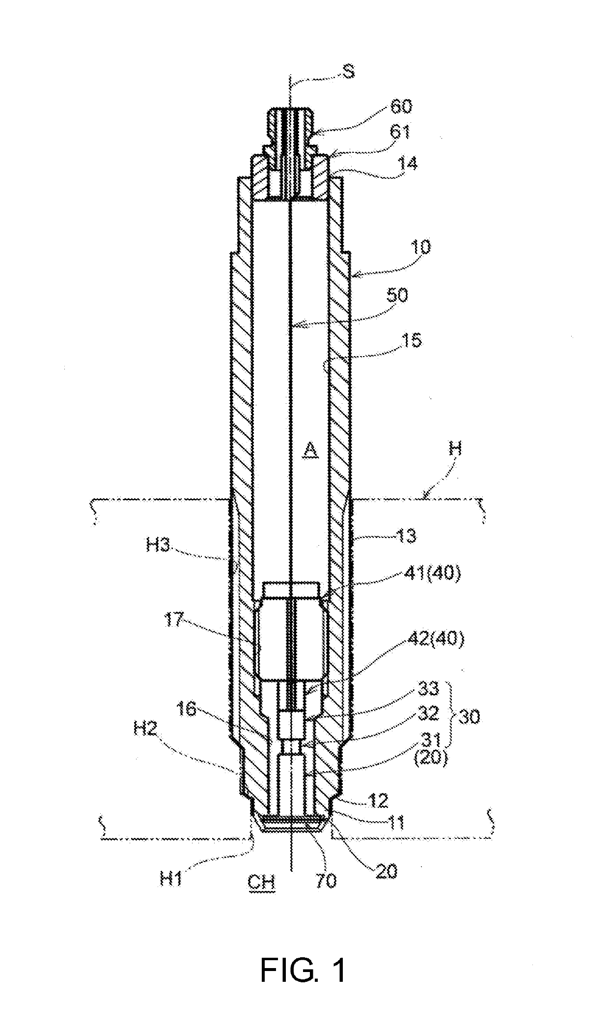
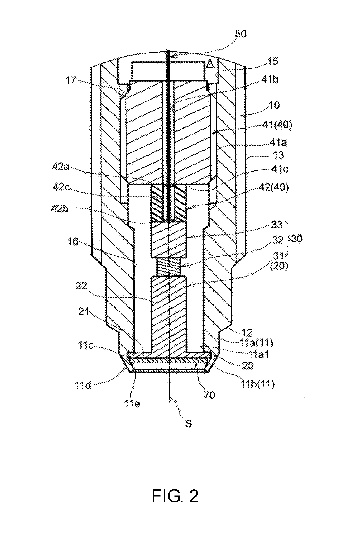
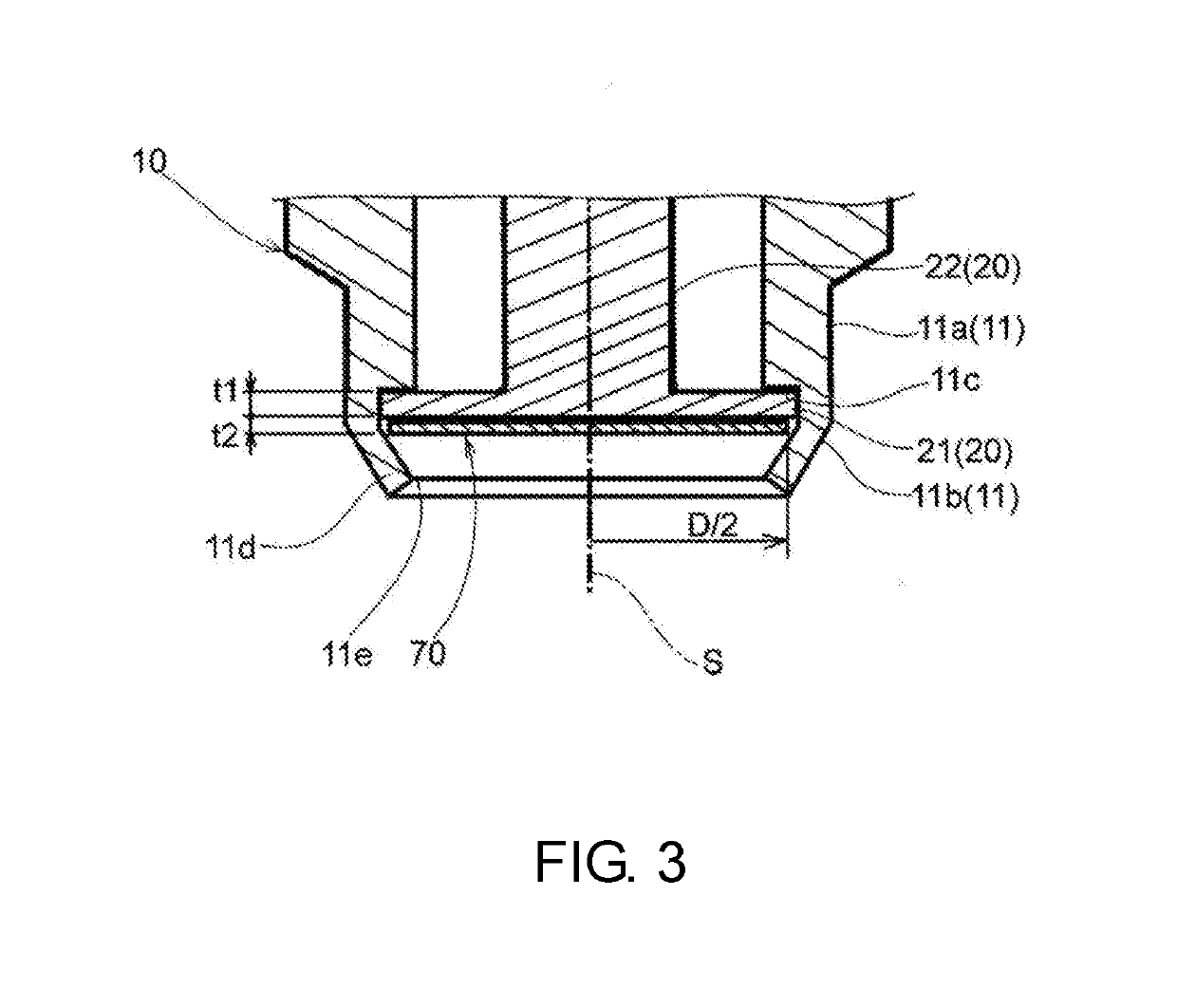
[0017]The embodiments of the disclosure are directed to providing a pressure sensor capable of securely shielding a diaphragm from a high temperature pressure medium, minimizing an influence of heat and accurately detecting a pressure of the high temperature pressure medium.

[0018]A pressure sensor of an embodiment of the disclosure includes a housing including a tubular tip portion; a pressure measuring part including a piezoelectric substance while being accommodated in the housing; a diaphragm including a flexible plate-shaped section fixed to an inner side of the tubular tip portion and a rod section interposed between the flexible plate-shaped section and the pressure measuring part; and a heat shield plate held on an inner side of the tubular tip portion to shield the diaphragm from a pressure medium.

[0019]In the pressure sensor having this configuration, the tubular tip portion may include an annular tip portion that defines an opening having a reduced diameter at a tip thereo...


PUM


Abstract

Provided is a pressure sensor capable of minimizing an influence of heat and accurately detecting a pressure of a high temperature pressure medium. The pressure sensor includes a housing including a tubular tip portion, a pressure measuring part including a piezoelectric substance while being accommodated in the housing, and a diaphragm including a flexible plate-shaped section fixed to an inner side of the tubular tip portion and a rod section interposed between the flexible plate-shaped section and the pressure measuring part, wherein a heat shield plate held on the inner side of the tubular tip portion to shield the diaphragm from a pressure medium is provided. Accordingly, an influence of heat can be minimized, and a pressure of a high temperature pressure medium can be accurately detected.

Description

CROSS-REFERENCE TO RELATED APPLICATION[0001]This application claims the priority of Japan patent application serial no. 2017-246118, filed on Dec. 22, 2017. The entirety of the above-mentioned patent application is hereby incorporated by reference herein and made a part of this specification.BACKGROUNDTechnical Field[0002]The disclosure relates to a pressure sensor configured to detect a pressure of a pressure medium, and more particularly, to a pressure sensor configured to detect a pressure of a high temperature pressure medium such as a combustion gas or the like in a combustion chamber of an engine.Description of Related Art[0003]As a pressure sensor in the related art, a pressure sensor including a tubular housing, a diaphragm bonded to a tip side of the housing and bent according to the received pressure, a sensor part disposed in the housing, a connecting part configured to connect the diaphragm to the sensor part, and a heat receiving part serving as a heat shield plate conn...

Claims


Application Information

Patent Timeline
IPC IPC(8): G01L9/00G01L19/04G01L23/10G01L23/22
CPCG01L9/008G01L9/0044G01L9/006G01L19/04G01L23/10G01L23/22G01L2019/0053G01L1/18
Inventor FUKUI, KATSUHIKO
Owner MIKUNI CORP
Learn More