
Lateral-type vacuum deposition apparatus, and source block and source assembly for the same

a vacuum deposition and lateral-type technology, applied in vacuum evaporation coatings, solid-state devices, coatings, etc., can solve the problems of replacement of conduits and collapsed powder-type sources, and achieve the effect of simple apparatus structure and excellent shape maintenance ability

Pending Publication Date: 2020-04-16
LG DISPLAY CO LTD
View PDF2 Cites 0 Cited by
  • Summary
  • Abstract
  • Description
  • Claims
  • Application Information

AI Technical Summary

Benefits of technology

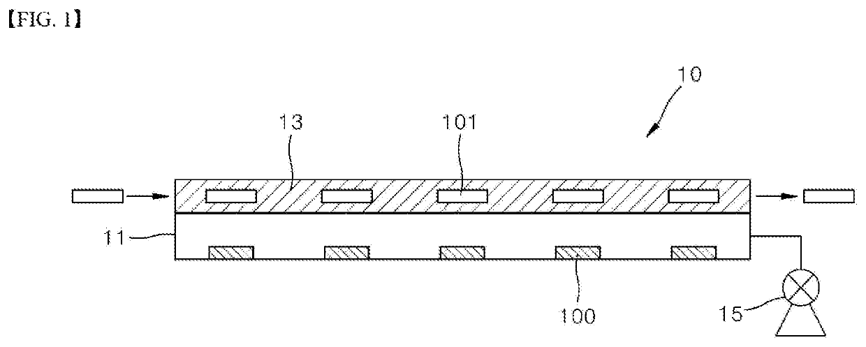
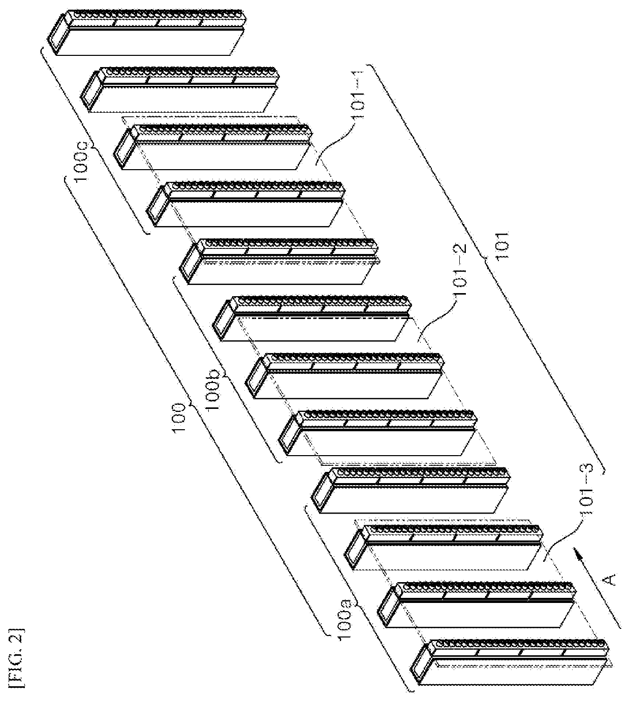
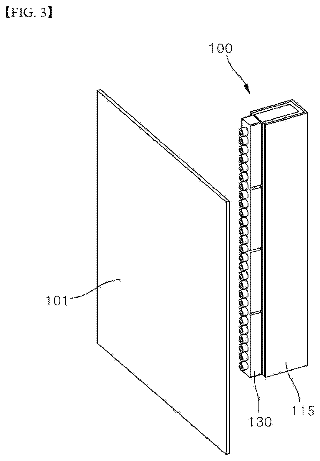
The present invention is about a lateral-type vacuum deposition scheme that improves the continuous deposition process and solves the substrate sagging problem. The use of a source block with good visual light transmission and high fracture strength is recommended to maintain its shape during the deposition process. A cooling plate or thermal-insulating plate can be added to minimize heat transfer between adjacent source assemblies. The source block is a molded block with a predetermined shape that simplifies the structure of the apparatus. Overall, the lateral-type vacuum deposition apparatus described in this patent offers improved efficiency and stability in the deposition process.

Problems solved by technology

The inventors of the present disclosure have recognized that when the powder type source block is applied to the lateral-type vacuum deposition apparatus, there occur problems that the powder type source collapses; and the source material is deposited on an inner wall of the conduit in the vacuum deposition process, thus requiring frequently cleaning to remove the source block material deposited on the inner wall of the conduit.
Further, the inventors of the present disclosure have recognized that as the cleaning process is frequently performed, corrosion of the conduit is problematic, thus requiring periodic replacement of the conduit.

Method used


Image

  • Lateral-type vacuum deposition apparatus, and source block and source assembly for the same
  • Lateral-type vacuum deposition apparatus, and source block and source assembly for the same
  • Lateral-type vacuum deposition apparatus, and source block and source assembly for the same

Examples


example

[0072]A configuration and operation of the present disclosure shall be described in more detail below using one Example of the present disclosure. However, this Example is presented merely as one example of the present disclosure and cannot be construed as limiting the present disclosure in any way. Those skilled in the art will be able to technically deduce contents as not described herein, so that the description thereof will be omitted.

[0073]1. Source Block Production

[0074](1) Powders of a hole injecting layer (HIL) material, a hole transport layer (HTL) material, a red light-emitting layer material, a green light emitting layer material, a blue light-emitting layer material, an electron transport layer (ETL) material, and an electron injection layer material (EIL) material were respectively provided.

[0075](2) The powders were subjected to a compression molding process using a press to produce a compression-molded source block. Alternatively, the powders were subjected to melting...


PUM

PropertyMeasurementUnit
Transmittivityaaaaaaaaaa
Shapeaaaaaaaaaa
Transport propertiesaaaaaaaaaa

Abstract

The present disclosure relates to a lateral-type vacuum deposition apparatus, and a source block and a source assembly for the same. Disclosed are a source block that may simplify a lateral-type vacuum deposition apparatus and a lateral-type vacuum deposition apparatus using the same. The source block has a predetermined shape. In the lateral-type vacuum deposition apparatus, the substrate and the source block may face away each other. Accordingly, the lateral-type vacuum deposition apparatus including the source block is free of a conduit for transferring a vaporized source to a nozzle, thereby simplifying a structure of the apparatus. In particular, the source block may have a visible light transmittance of at least about 10% and may exhibit excellent shape maintenance ability during a lateral-type vacuum deposition process.

Description

CROSS-REFERENCE TO RELATED APPLICATIONS[0001]This application claims the priority of Korean Patent Application No. 10-2018-0120580 filed on Oct. 10, 2018, in the Korean Intellectual Property Office, the disclosure of which is hereby incorporated by reference in its entirety.BACKGROUNDTechnical Field[0002]The present disclosure relates to a vacuum deposition apparatus.Description of the Related Art[0003]As display technology is developed, a flat panel display device is widely used. The flat panel display device includes a liquid crystal display device, an electroluminescence display device, and the like. The liquid crystal display device requires a backlight unit as a separate light source block and has technical limitations in terms of brightness and contrast ratio. Therefore, interest in the electroluminescence display device is increasing which is relatively superior to the liquid crystal display device in terms of brightness and contrast ratio and realizes a self-light emission a...

Claims


Application Information

Patent Timeline
IPC IPC(8): C23C14/24H01L51/56
CPCC23C14/24H01L51/56C23C14/246C23C14/12H10K71/164H10K71/40C23C14/243C23C14/26H10K71/00
Inventor SEO, JI-MANJEONG, HOYOUNGPARK, JAEWOOK
Owner LG DISPLAY CO LTD
Learn More