Secondary battery

Active Publication Date: 2019-06-27
TOYOTA JIDOSHA KK
View PDF2 Cites 2 Cited by
  • Summary
  • Abstract
  • Description
  • Claims
  • Application Information

AI Technical Summary

Benefits of technology

The patent text discusses a problem where a secondary battery may be damaged when its casing is short-circuited. To address this problem, the disclosure provides a secondary battery with a cut-off portion that can prevent current flow if the casing is short-circuited. The cut-off portion can be composed of an insulating member and a melting member, which helps to electrically cut off the casing and one terminal without causing excess damage. Additionally, the cut-off portion can be designed to deform or warp when the battery is short-circuited, increasing contact resistance and reducing the area of contact in order to further prevent damage. The technical effects of the patent text include increased safety and reliability, simplified and efficient design, and reduced installation space.

Problems solved by technology

However, when the current cut-off mechanism is provided between the casings of the secondary batteries or provided to span the casings adjacent to each other, the mechanism becomes large-scaled, and the manufacturing coat thereof also increases.

Method used


Image

  • Secondary battery
  • Secondary battery
  • Secondary battery

Examples


first embodiment

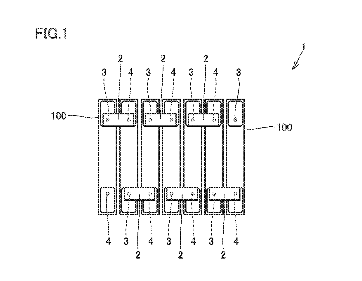
[0028]FIG. 1 is a plan view showing a battery pack in accordance with a first embodiment. Referring to FIG. 1, a battery pack 1 in accordance with the first embodiment will be described.

[0029]As shown in FIG. 1, battery pack 1 is constituted of a plurality of chargeable / dischargeable secondary batteries 100 connected in series. In battery pack 1, the plurality of secondary batteries 100 having the same shape are connected in series to constitute battery pack 1. It should be noted that the number of secondary batteries 100 constituting battery pack 1 is not particularly limited.

[0030]Secondary batteries 166 are aligned to be spaced from each other. The plurality of secondary batteries 100 are aligned such that side surfaces having the largest area of secondary batteries 100 face each other. In a gap between two adjacent secondary batteries 100, a cooling plate, a cushioning plate, or the like not shown is arranged.

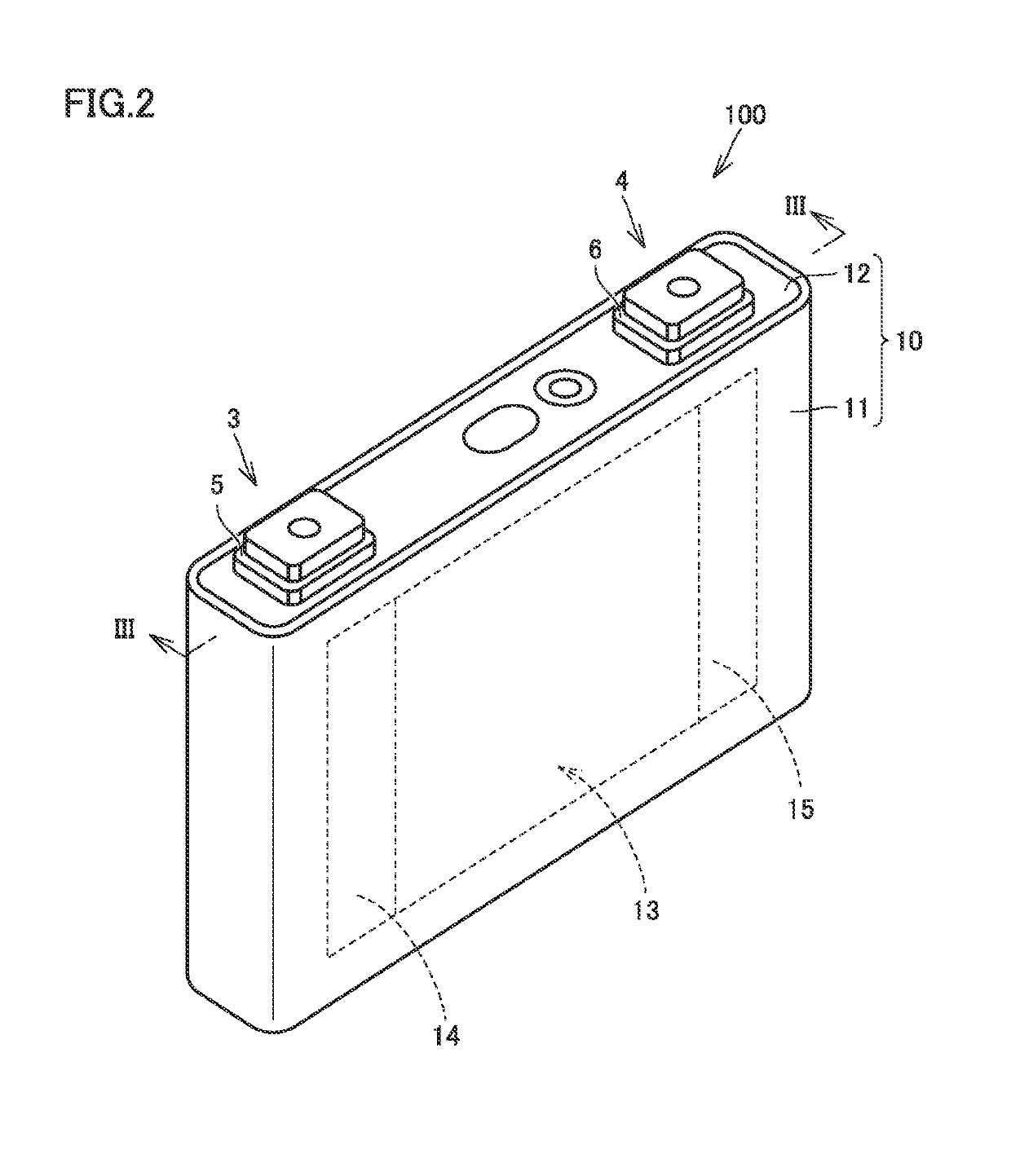
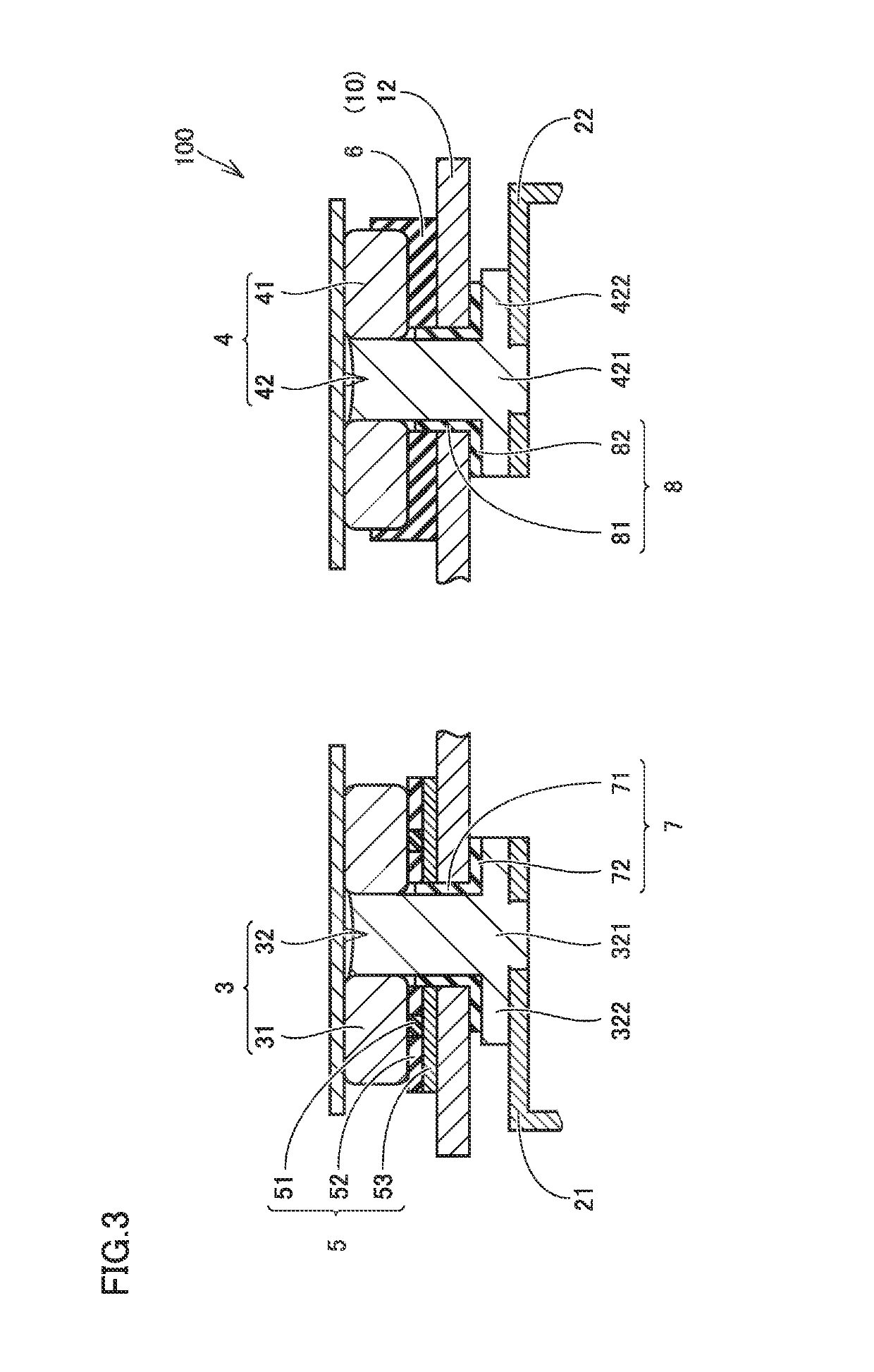
[0031]Secondary battery 100 has a terminal 3 for a positive electrode ...

second embodiment

[0065]FIG. 7 is a cross sectional view showing a configuration on a positive electrode terminal side of a secondary battery in accordance with a second embodiment. Referring to FIG. 7, a secondary battery 100A in accordance with the second embodiment will be described. p As shown in FIG. 7, secondary battery 100A in accordance with the second embodiment is different from secondary battery 100 in accordance with the first embodiment in the configuration of a cut-off portion 5A. Other components are substantially identical.

[0066]Cut-off ports on 5A has a resin layer 51A having electrical conductivity and heat resistance, a first metal layer 52A, and a second metal layer 53A. Resin layer 51A, first metal layer 52A, and second metal layer 53A are stacked in a facing direction in which external terminal 31 faces seal plate 12. Second metal layer 53A, first metal layer 52A, and resin layer 51A are stacked in order from the seal plate 12 side.

[0067]Resin layer 51A, first metal layer 52A, a...


PUM


Abstract

A secondary battery includes: a battery element; a casing which accommodates the battery element; a positive electrode terminal and a negative electrode terminal provided to the casing and electrically connected to the battery element; and a cut-off portion which switches from a grounded state in which the casing and one terminal of the positive electrode terminal and the negative electrode terminal have an identical potential, to a cut-off state in which the casing and the one terminal are electrically cut off. The one terminal has a facing portion which faces the casing, and the cut-off portion is arranged between the facing portion and the casing. When the casing is externally short-circuited, the cut-off portion switches from the grounded state to the cut-off state by being deformed by heat generated as a short-circuit current flows.

Description

CROSS REFERENCE TO RELATED APPLICATIONS[0001]This nonprovisional application claims priority to Japanese Patent Application 2017-249077 filed on Dec. 26, 2017 with the Japan Patent Office, the entire contents of which are hereby incorporated by reference.BACKGROUNDField[0002]The present disclosure relates to a secondary battery.Description of the Background Art[0003]Conventionally, there have been developed various types of secondary batteries provided with a short circuit mechanism which establishes a short circuit between an external terminal for a positive electrode and an external terminal for a negative electrode when an internal pressure of a casing increases. Such a secondary battery is disclosed, for example, in Japanese Patent Laying-Open No. 2015-082500.[0004]In the secondary battery disclosed in Japanese Patent Laying-Open No. 2015-082500, in a current collecting member which electrically connects a positive electrode of a battery element and an external terminal for the ...

Claims


Application Information

Patent Timeline
IPC IPC(8): H01M2/30H01M2/10H01M2/04H01M2/34H01M2/20H01M50/209H01M50/505H01M50/51H01M50/55H01M50/553H01M50/574H01M50/588H01M50/593
CPCH01M2/30H01M2/1077H01M2/0486H01M2/34H01M2/206H01M50/553H01M50/55H01M50/593H01M50/588H01M50/51H01M50/574H01M50/505H01M50/209Y02E60/10H01M50/581
Inventor ASAKURA, KAZUMATAKEI, YASUYUKI
Owner TOYOTA JIDOSHA KK
Why Eureka
Try Eureka