Auxiliary visible light wand for multisource PET CO2 monitoring

A light rod and rod body technology, applied in the field of medical devices, can solve the problems of lack of auxiliary methods, negative effects of operation, imperfection, etc., and achieve the effects of reducing the probability of bacterial infection, being less prone to secondary damage, and improving stability.

Active Publication Date: 2020-02-21
SHANGHAI NINTH PEOPLES HOSPITAL AFFILIATED TO SHANGHAI JIAO TONG UNIV SCHOOL OF MEDICINE
View PDF8 Cites 2 Cited by
  • Summary
  • Abstract
  • Description
  • Claims
  • Application Information

AI Technical Summary

Problems solved by technology

However, this method is not perfect due to its own technology, and although it can cooperate with sensing devices to detect multi-source end-exhalation CO 2 Monitoring, but it is highly dependent on the accuracy of the equipment, the deviation of the sensor position, the failure of the sensor itself, or the disorder of the data analysis system will have a negative impact on the operation; and there is a lack of intuitive and visible auxiliary methods
The existing light sticks are portable, economical, and can solve most of the difficult problems of intubation, but they also have disadvantages, for example: first, they lack visibility and can only rely on light sources for position determination, and lack direct access to the internal environment. Observation; Secondly, during the insertion and extraction process of the light rod, it rubs against the airway, and when the patient's resistance is poor or the light rod's own bacteria exceed the standard, it is very easy to appear redness or inflammation

Method used


Image

  • Auxiliary visible light wand for multisource PET CO2 monitoring
  • Auxiliary visible light wand for multisource PET CO2 monitoring
  • Auxiliary visible light wand for multisource PET CO2 monitoring

Examples


Embodiment Construction

[0027] The specific implementation manners of the present invention will be described in further detail below in conjunction with the embodiments and accompanying drawings. Here, the following examples of the present invention are used to illustrate the present invention, but not to limit the scope of the present invention.

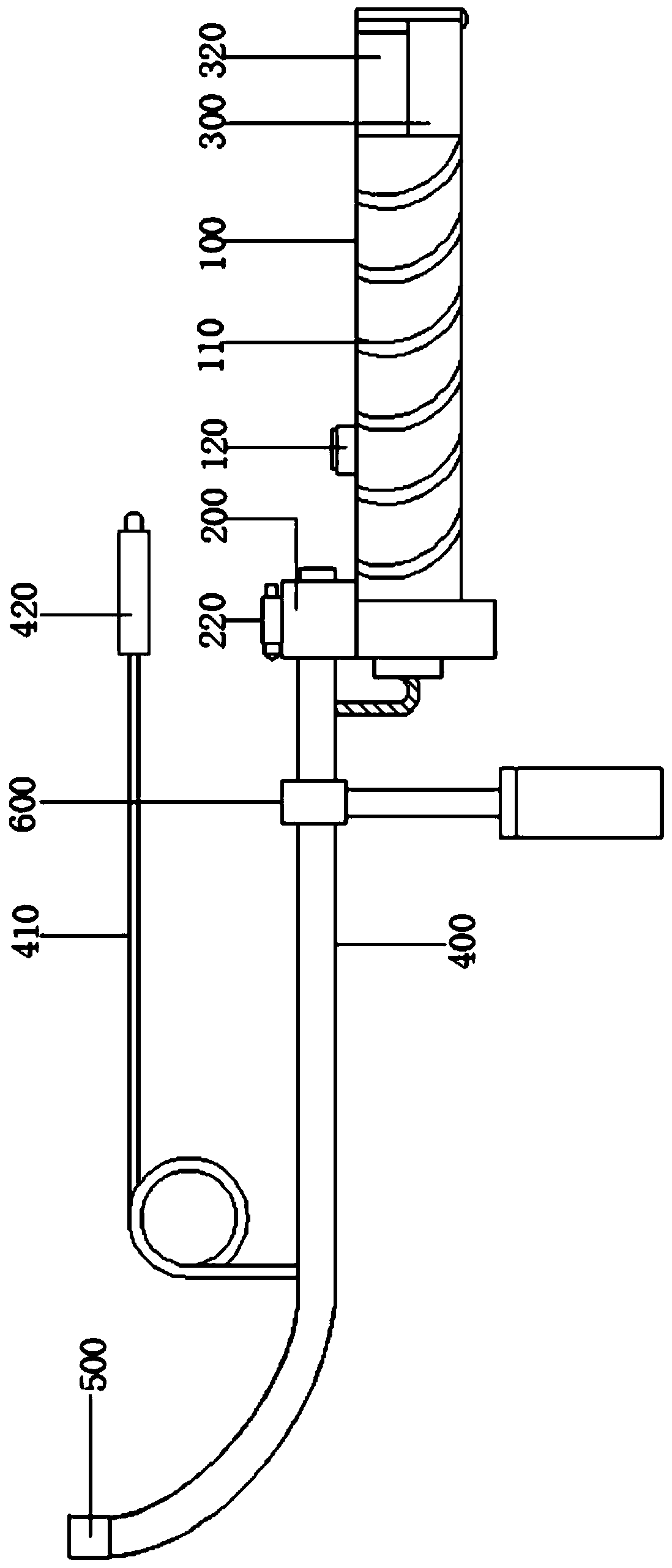
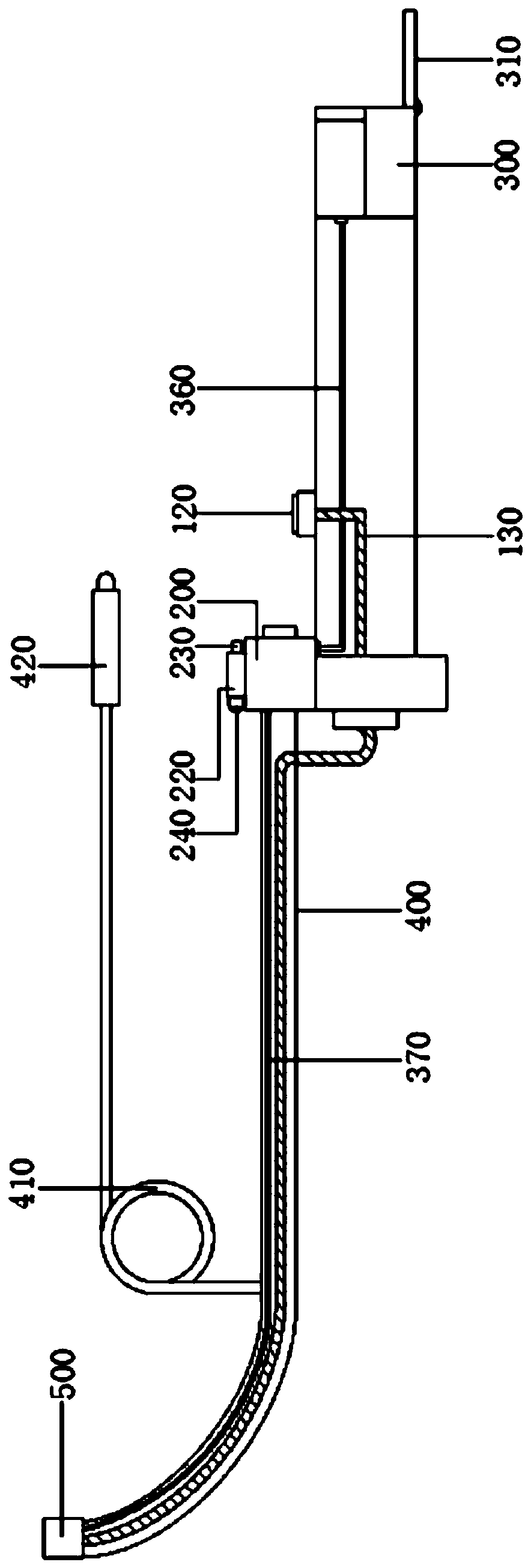
[0028] Such as figure 1 and figure 2 As shown, a multi-source end-call CO provided by the embodiment of the present invention 2 The monitoring auxiliary visible light stick includes: a handle 100 , a pump body 200 , a medicine compartment 300 , and a stick body 400 . One end of the handle 100 is connected to the pump body 200 , and the other end is connected to the medicine compartment 300 , and a first button 120 is arranged on the handle 100 . The pump body 200 is connected with the rod body 400 and the atomizing tube 370 disposed in the rod body 400 , and the pump body 200 is provided with a second button 210 . In this embodiment, the pump body 20...


PUM


Abstract

The invention discloses an auxiliary visible light wand for multisource PET CO2 monitoring. The auxiliary visible light wand comprises a handle, a pump body, a medicine bin, a wand body and a bracket.The handle is separately connected with the medicine bin, the pump body and the wand body, and one end of the wand body is connected with a wand head. A lamp and an atomizer head are arranged in thewand head. A circuitron is connected with the external wall of the wand body, one end of the circuitron is connected with a display screen, and the other end of the circuitron is connected with a camera in the wand head. The bracket sleeves the wand body and is fixed to the outer side of an oral cavity or a chin of a patient, and thus, the stability of the wand body is improved. Through the matching of all the components, the interior of a trachea of the patient can be observed during tracheal intubation, and thus, the difficulty resulting from direct laryngoscope intubation is avoided. Through being effectively matched with tracheal intubation, the tracheal intubation can be high in accuracy and short in consumed time, and secondary injury to the patient is difficultly caused. Inflammation diminishing medicines in the medicine bin can be sprayed inside the trachea of the patient through the atomizer head by the pump body, and thus, the aims of alleviating and resisting inflammations and lowering the bacterial infection probability of the trachea and discomfort of the patient are exerted.

Description

technical field [0001] The invention relates to the technical field of medical devices, in particular to a multi-source end-exit CO 2 Monitoring Auxiliary Visible Light Stick. Background technique [0002] Tracheal intubation is the most effective and reliable method to establish an artificial airway, and it is an essential technique for general anesthesia and emergency recovery. [0003] The traditional intubation method is to use a direct laryngoscope to intubate under direct vision, but the airway conditions of patients vary greatly, and the intubation conditions are not good (for example, small mandible, short thyromental distance, elevating glottis, small mouth opening, cervical For patients with limited internal mobility), direct laryngoscope intubation is often very difficult; the failure rate of the first intubation is high, and repeated attempts are required, which takes a long time and is likely to cause secondary injury to the patient. [0004] Aiming at the abo...

Claims


Application Information

Patent Timeline
Patent Type & Authority Applications(China)
IPC IPC(8): A61B1/267A61B1/04A61B1/06A61M16/04A61M11/00A61M31/00
CPCA61B1/2676A61B1/04A61B1/0661A61M16/04A61M11/00A61M31/00A61B1/00064A61B1/00131A61B1/00147A61M2210/1032A61M2210/005A61B1/267A61B1/07A61B1/05A61B1/00096A61B5/0836A61B5/0077A61B5/6852A61B5/0803A61M16/0488A61M2016/0413A61M2202/0468A61M11/006A61M11/003
Inventor 姜虹夏明孙宇严佳
Owner SHANGHAI NINTH PEOPLES HOSPITAL AFFILIATED TO SHANGHAI JIAO TONG UNIV SCHOOL OF MEDICINE
Why Eureka
Try Eureka