

Cluster assembly and electric compressor comprising same
a technology of electric compressor and cluster assembly, which is applied in the direction of positive displacement liquid engine, piston pump, liquid fuel engine, etc., can solve the problems of weak insulation ability between the three terminals and the increased space of the increased size, so as to improve the insulation structure of the cluster, prevent short circuit, and be easily equipped in the electric motor
Active Publication Date: 2019-07-04
HANON SYST
View PDF4 Cites 4 Cited by
- Summary
- Abstract
- Description
- Claims
- Application Information
AI Technical Summary
Benefits of technology
The cluster assembly in this patent has improved insulation for the electric motor of a compressor. It includes a detachable cluster that is easy to install and a cluster body that surrounds the stator core. The space between the coil insertion holes and the terminals is filled with insulating material to prevent refrigerant from flowing into the terminals and to prevent short circuits. The detachable cluster simplifies the connection process between the coil and terminals, reducing assembly time and manufacturing costs. The cluster body and detachable cluster do not require separate fixing means and reduce the need for additional components.
Problems solved by technology
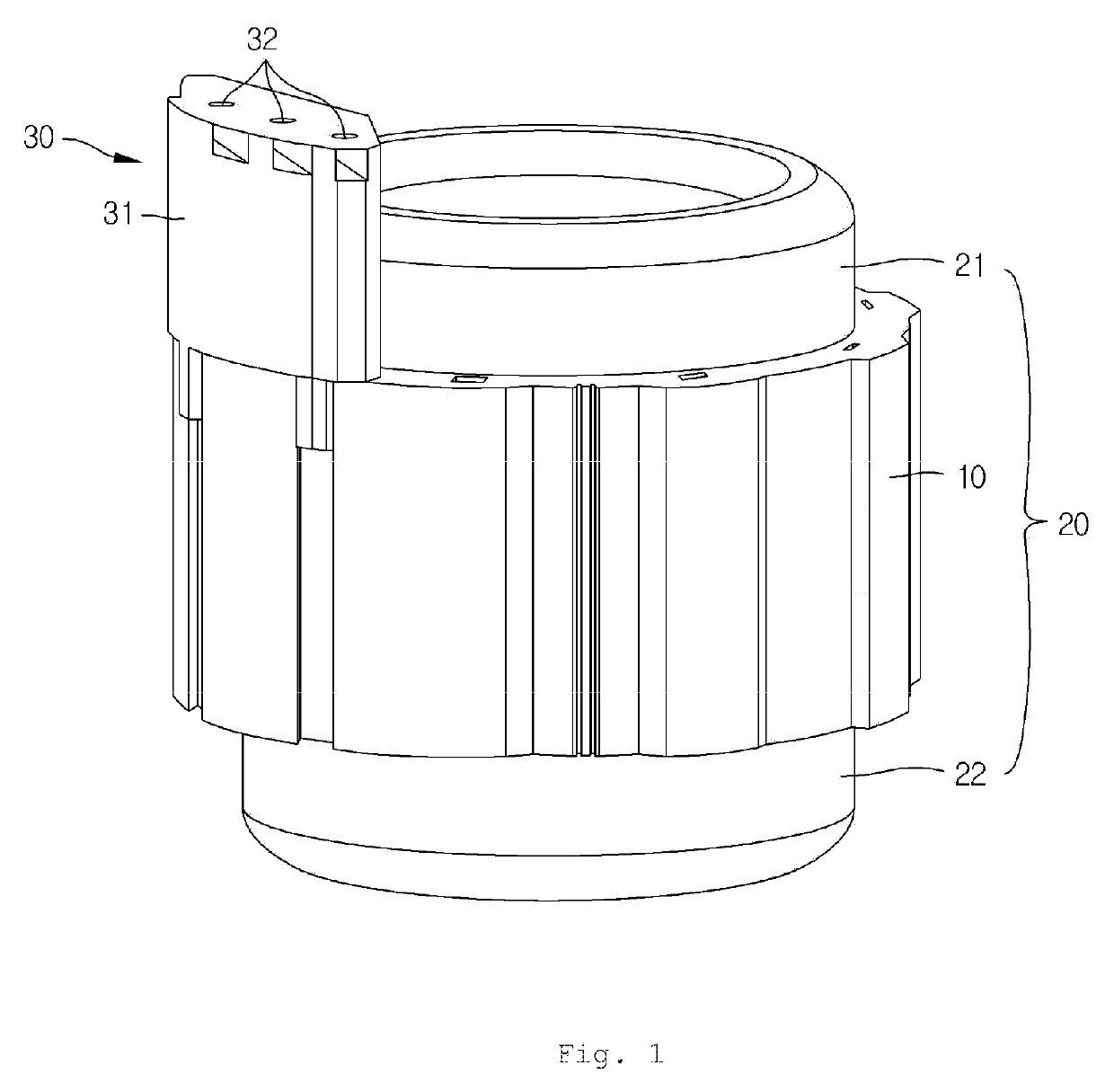
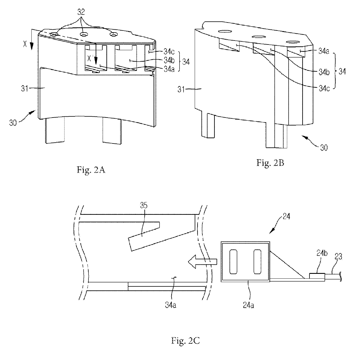
In such a configuration, there is a high possibility that a refrigerant existing in a gas or liquid state in the compressor is directly in contact with the terminals 24 and current leaks through the refrigerant, and there is a high possibility that weakness of insulating ability between the three terminals 24 is caused.
Further, since the electric compressor having the terminal housing equipped on an outer circumference surface as illustrated in FIG. 1 has the size of the package increased externally by the size of the terminal housing, it has a disadvantage that it should have more space for the increased size.
Method used
View moreImage
Smart ImageViewing Examples

Examples
Embodiment Construction
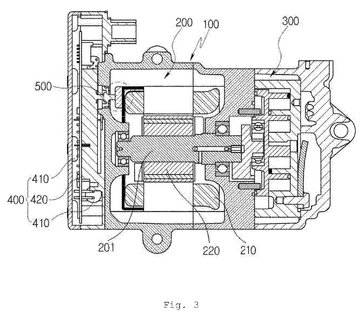
[0080]1: electric compressor
[0081]100: housing
[0082]200: electric motor
[0083]201: driving shaft
[0084]210: stator
[0085]211: fixing slot
[0086]220: rotor
[0087]230: coil
[0088]300: compression mechanism part
[0089]400: motor driving circuit
[0090]410: circuit element
[0091]420: circuit board
[0092]500: cluster assembly
[0093]510: terminal
[0094]520: detachable cluster
[0095]521: upper cluster
[0096]522: lower cluster
[0097]531, 532, 533: first to third coil fixing parts
[0098]541, 542, 543: first to third terminal accommodating parts
[0099]560: cluster body
[0100]561: fixing protrusion
[0101]562: lead wire fixing part
[0102]563: refrigerant passage hole
[0103]564: cluster inserting part
[0104]571, 572, 573: first to third leading holes
Login to View More PUM
 Abstract
The present invention relates to a cluster assembly and an electric compressor comprising the same and, more particularly, to a cluster assembly which has an improved insulation structure and is convenient to install, and an electric compressor comprising the same. More specifically, the cluster assembly comprises: three terminals; a detachable cluster including first to third coil fixing portions each having a coil insertion hole into which a coil end is insertedly formed therein, and first to third terminal receiving portions having a space formed therein so as to be spaced apart from the first to third coil fixing portions by a predetermined distance in the longitudinal direction of the coil and receive the terminals; and a cluster body which is coupled to one side surface of an electric motor in an axial direction and is formed hollow in the center thereof along the outer circumferential surface of a stator and which includes a cluster insertion portion formed corresponding to the shape of the detachable cluster so that the detachable cluster can be inserted in a horizontal direction.
Description
RELATED APPLICATIONS[0001]This application is a national phase under 35 U.S.C. § 371 of International Application No. PCT / KR2017 / 002718 filed Mar. 14, 2017, which claims the benefit of priority from Korean Patent Application No. 10-2016-0108057 filed Aug. 25, 2016 in the Republic of Korea. The entire contents of these applications are incorporated herein by reference in their entirety.TECHNICAL FIELD[0002]The present invention relates to a cluster assembly and an electric compressor including the same, and more particularly, to a cluster assembly that has an improved insulation structure and is easily equipped and an electric compressor including the same.BACKGROUND ART[0003]In accordance with a low pollution and high fuel efficiency policy due to the depletion of fossil fuels and environmental pollution, hybrid vehicles or electric vehicles, which use both fossil fuel and electricity as a driving source, are recently highlighted, and researches for the hybrid vehicles or the electr...
Claims
Login to View More Application Information
Patent Timeline
 Patent Type & Authority Applications(United States)
IPC IPC(8): F04C23/02H02K11/00H02K3/50F04C29/00H02K5/22
CPCF04C23/02H02K11/00H02K3/50F04C29/005F04C29/0085H02K5/225F04C2240/40F04C2240/30F04C29/00H02K5/22H02K3/522H02K3/38H02K2203/06F04B35/04
Inventor HEO, JEONG GILTAGAMI, SHINJISEO, BONG KYUN
Owner HANON SYST