Punched sheet, iron core and motor

A punching and iron core technology, which is applied in the field of motors, can solve the problems of poor versatility and achieve the effects of simple and reasonable structure, cost reduction, and enhanced insulation structure

Pending Publication Date: 2020-01-31
CHONGQING KAIBANG MOTOR +1
View PDF0 Cites 0 Cited by
  • Summary
  • Abstract
  • Description
  • Claims
  • Application Information

AI Technical Summary

Problems solved by technology

[0006] The invention provides a punching sheet, which is used to solve the technical problem of poor versatility caused by the punching sheet design scheme in the prior art which can only be applied to a motor of one specification

Method used


Image

  • Punched sheet, iron core and motor
  • Punched sheet, iron core and motor
  • Punched sheet, iron core and motor

Examples


Embodiment 1

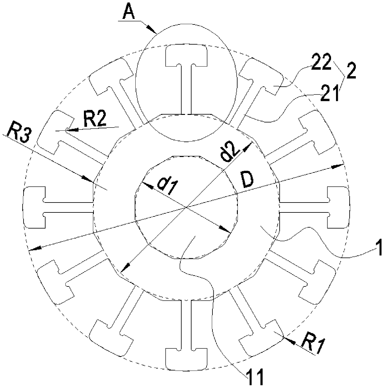
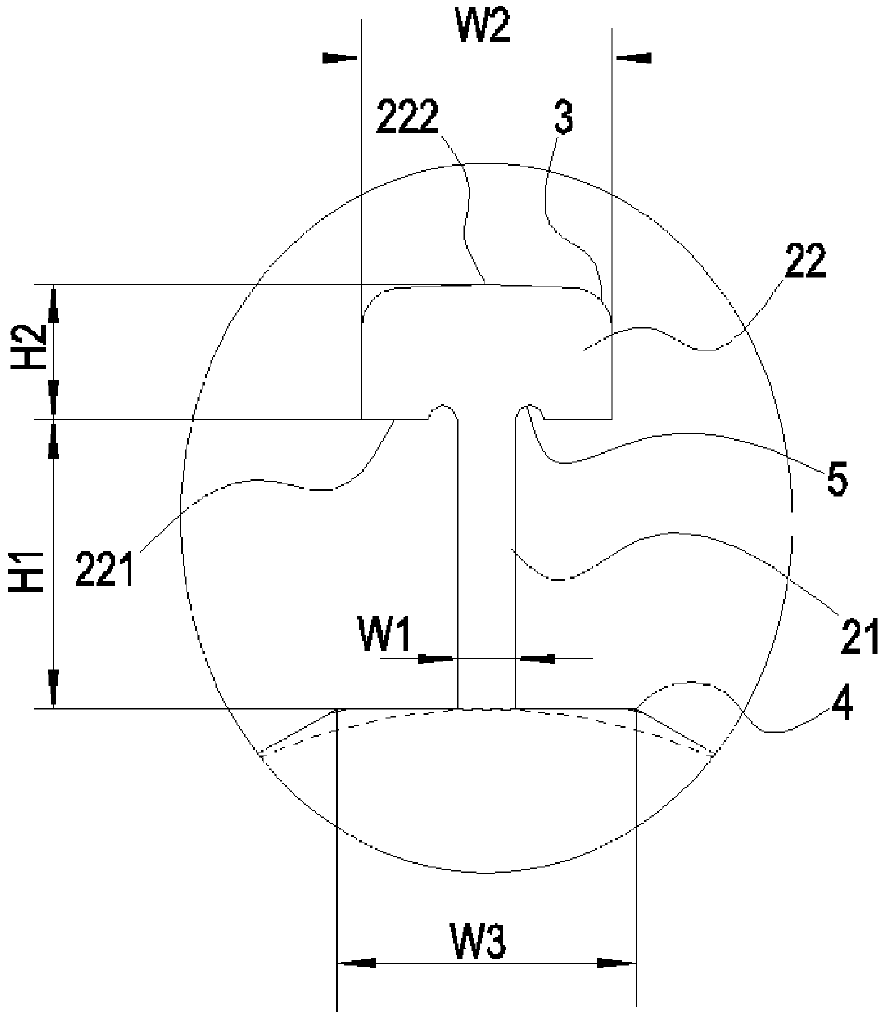
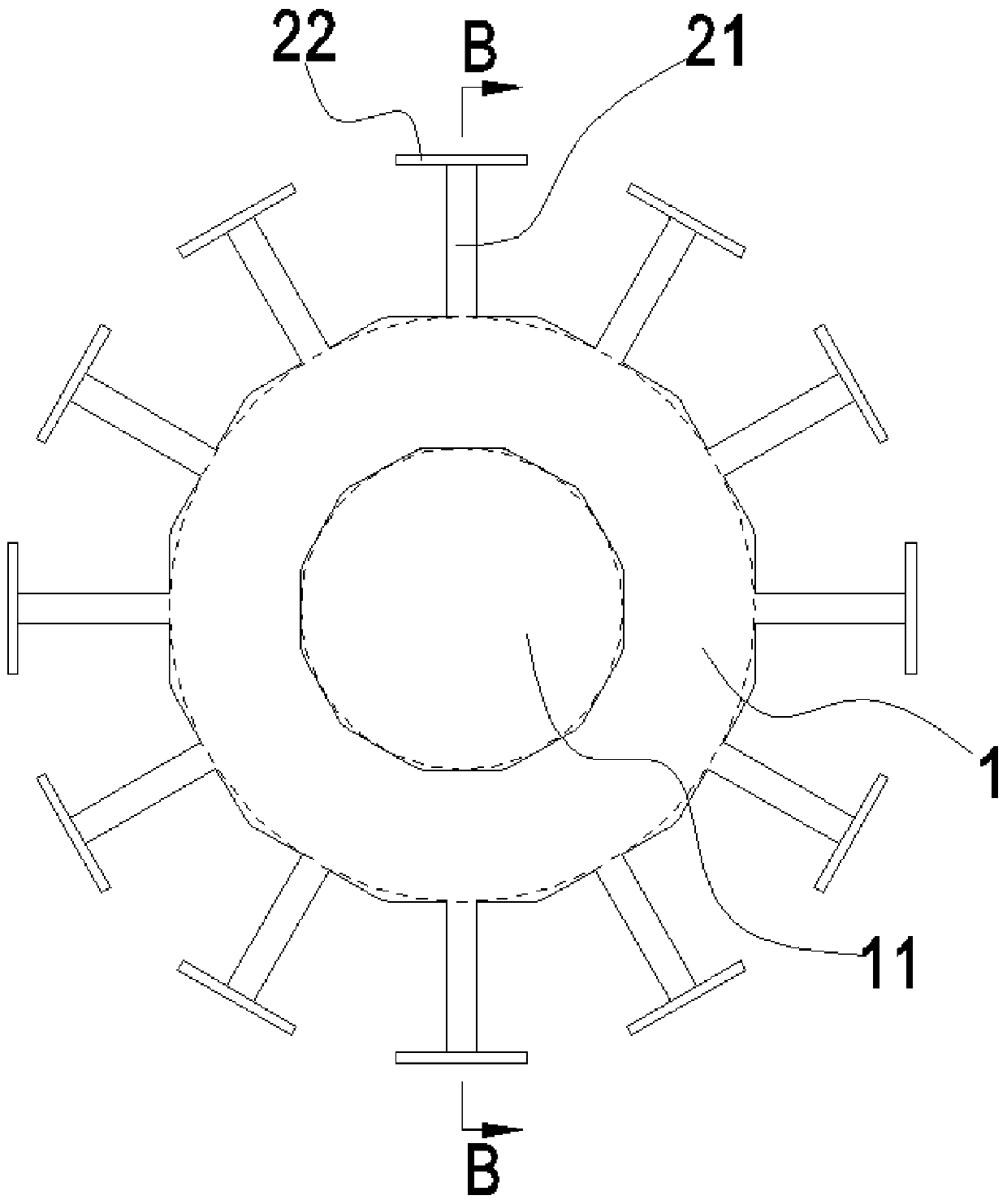
[0038] The present invention provides a punching sheet, which includes a punching sheet main body 1 and a plurality of tooth yoke bodies 2 uniformly distributed on the outer circumference of the punching sheet main body 1. It is worth noting that the punching sheet main body 1 and the tooth yoke main body 2 are integrally formed. . The tooth yoke main body 2 includes a tooth body part 21 connected to the punch body 1 and a tooth end part 22 connected to the end of the tooth body part 21, and the tooth yoke main body 2 is composed of a tooth body part 21 and a tooth end part 22. , the tooth body portion 21 is connected to the middle position of the tooth end portion 22 , that is, the sections of the tooth end portion 22 located on both sides of the tooth body portion 21 are symmetrical.

[0039] The total width and total length of the tooth end portion 22 are respectively W2 and H2, the tooth body portion 21 is a square sheet structure and the length and width of the tooth body...

Embodiment 2

[0042] This embodiment is a best implementation mode of Embodiment 1. The punching body 1 in this embodiment is a regular polygonal structure, and the center position of each side of the facing structure is respectively provided with the above-mentioned tooth yoke main body 2, In this way, the side connecting the tooth yoke main body 2 is straight. In this embodiment, the side of the tooth end portion 22 close to the punch body 1 is a plane 221 , and the plane 221 is parallel to the side corresponding to the regular polygonal structure. With this structure, a rectangular winding chamber is formed between the tooth end portion 22 and the corresponding side of the regular polygonal structure, so that the coils wound in the chamber can be more evenly placed in each position of the chamber.

[0043] Certainly, the above punching body 1 may also have a circular structure.

[0044] More preferably, in this embodiment, the side length of the punching body 1 is defined as W3, W3≥(4 / 5...

Embodiment 3

[0046] This embodiment is a more optimal implementation mode of Embodiment 2. The center of the punching body 1 in this embodiment is provided with a through hole 11. The through hole 11 can be a circular hole or a regular polygonal hole, and the through hole 11 is limited. The diameter of the hole 11 is d1, and the diameter of the inscribed circle that limits the punching body 1 is d2, the diameter of the entire punching sheet is D (also the diameter of the circumscribed circle of the entire punching sheet is D), d2>(1 / 2)× D, d1>(1 / 2)×d2.

[0047] As another implementation of this embodiment, the center of the punching body 1 is solid, that is, the through hole 11 is not provided.

[0048]It should be noted that a specific implementation of this embodiment is as follows: the surface of the side of the tooth end portion 22 away from the punch body 1 is parallel to the plane 221 . As a preferred implementation of this embodiment, the surface of the tooth end portion 22 away fr...


PUM


Abstract

The invention relates to a punched sheet, an iron core and a motor and belongs to the technical field of motors. The punched sheet comprises a punched sheet main body and a plurality of tooth yoke main bodies uniformly distributed on the punched sheet main body; the tooth yoke main body comprises a tooth body part and a tooth end part; the total width and total length of the tooth end part are W2and H2 respectively; the length and width of the tooth body part are respectively H1 and W1; W2 is larger than 4*W1; and H1 is larger than 2*H2. The punched sheet with the above structure is suitablefor the design of a multi-pole motor punched sheet with 4-18 teeth and has high universality. The iron core comprises first punched sheets and second punched sheets; the plate surface of the tooth endpart of the first punched sheet and the plate surface of the tooth body part of the first punched sheet are flush with each other; the plate surface of the tooth end part of the second punched sheetand the plate surface of the tooth body part of the second punched sheet are perpendicular to each other; the plurality of first punched sheets are laminated to form a combined part; and two second punched sheets are laminated at two ends of the combined part respectively with the tooth end parts of the second punched sheets facing one side far away from the combined part. The iron core with the above structure has the advantages of larger magnetic conduction area, stronger magnetic induction, more concentrated magnetic flux and lower loss. With the iron core adopted, the motor has the advantages of higher energy efficiency, lower temperature rise and lower cost.

Description

technical field [0001] The invention belongs to the technical field of motors, and in particular relates to a punching sheet, an iron core and a motor. Background technique [0002] A DC motor is a motor that converts DC electrical energy into mechanical energy or a rotating electrical machine that converts mechanical energy into DC electrical energy. It is a device that can convert DC electrical energy and mechanical energy into each other. When it operates as a motor, it is a DC motor, which converts electrical energy into mechanical energy; when it operates as a generator, it is a DC generator, which converts mechanical energy into electrical energy. [0003] DC motor is widely used in electric drive because of its good speed regulation performance, and DC generator is widely used in power generation because of its convenient use, reliable operation, good potential waveform and small electromagnetic interference. [0004] According to the excitation method, DC motors are...

Claims


Application Information

Patent Timeline
Patent Type & Authority Applications(China)
IPC IPC(8): H02K1/06
CPCH02K1/06H02K2213/03
Inventor 唐旭辉刘克奇徐红升唐宗兵周浩李嘉
Owner CHONGQING KAIBANG MOTOR
Why Eureka
Try Eureka