
Pattern detection

a pattern detection and pattern technology, applied in image analysis, image enhancement, instruments, etc., can solve the problems of glare, vignetting effect, and very strong distortion effect of endoscopic applications, and achieve the effect of reducing the number of pixels

Active Publication Date: 2019-07-04
FRAUNHOFER GESELLSCHAFT ZUR FOERDERUNG DER ANGEWANDTEN FORSCHUNG EV
View PDF3 Cites 3 Cited by
  • Summary
  • Abstract
  • Description
  • Claims
  • Application Information

AI Technical Summary

Benefits of technology

This patent describes an improved calibration process for a camera, specifically an endoscopic camera. The process involves detecting a known pattern, called a calibration target, in a robust and precise manner. The detection is done in two stages: an initial estimation of the target is made using a discriminant criterion, followed by a refinement of the position of the target through the identification of features within adjacent regions. This approach works well even in the presence of distortion, image blur, noise, and partial visibility of the target. The patent also provides some details about the calculation of the discriminant criterion and its application in finding the first region of the known pattern. Overall, this patent provides a more accurate and reliable calibration process for cameras, particularly endoscopic cameras.

Problems solved by technology

Camera calibration for endoscopic applications poses several challenges.
Therefore, distortion effects are very strong.
This often causes strong inhomogeneity, glare, vignetting effects, and high image noise in badly illuminated regions.
Self-identifying targets (like ARTags [6]) are more complex and may use high resolution and low-noise images.
However, none of the above described concepts are robust enough to handle strong distortions, image blur, noise, and partially visible targets.

Method used


Image

  • Pattern detection
  • Pattern detection
  • Pattern detection

Examples


Embodiment Construction

[0050]Below, embodiments of the present invention will subsequently be discussed referring to the figures. Here, identical reference numbers are provided to elements or steps having identical or similar functions. Therefore, the description thereof is interchangeable and mutually applicable.

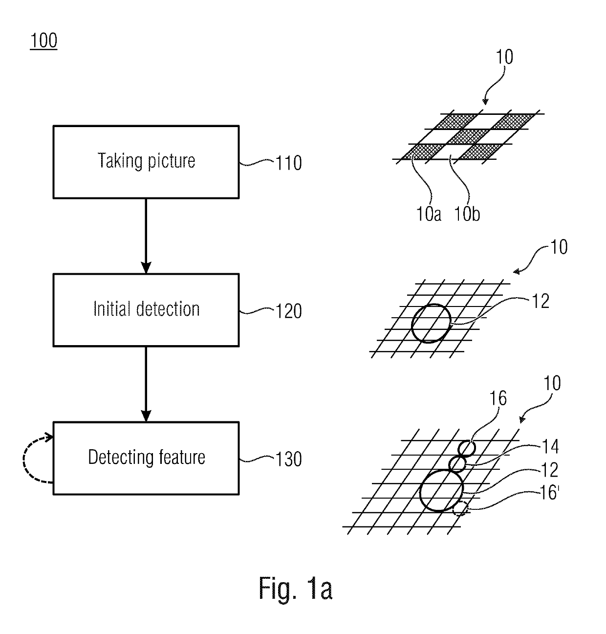
[0051]FIG. 1a shows the basic method 100 for detecting a known pattern 10 having homogeneous areas 10a and 10b. The known pattern 10 may be, for example, a chessboard or another regular or irregular pattern e.g. comprising circles or having QRcode arrangement. Typically, but unnecessarily, the areas 10a and 10b are black and white, such that the same offer a high contrast. However, according to further embodiments, the homogeneous areas may have a different color. The method 100 comprises the three basic steps 110, 120 and 130.

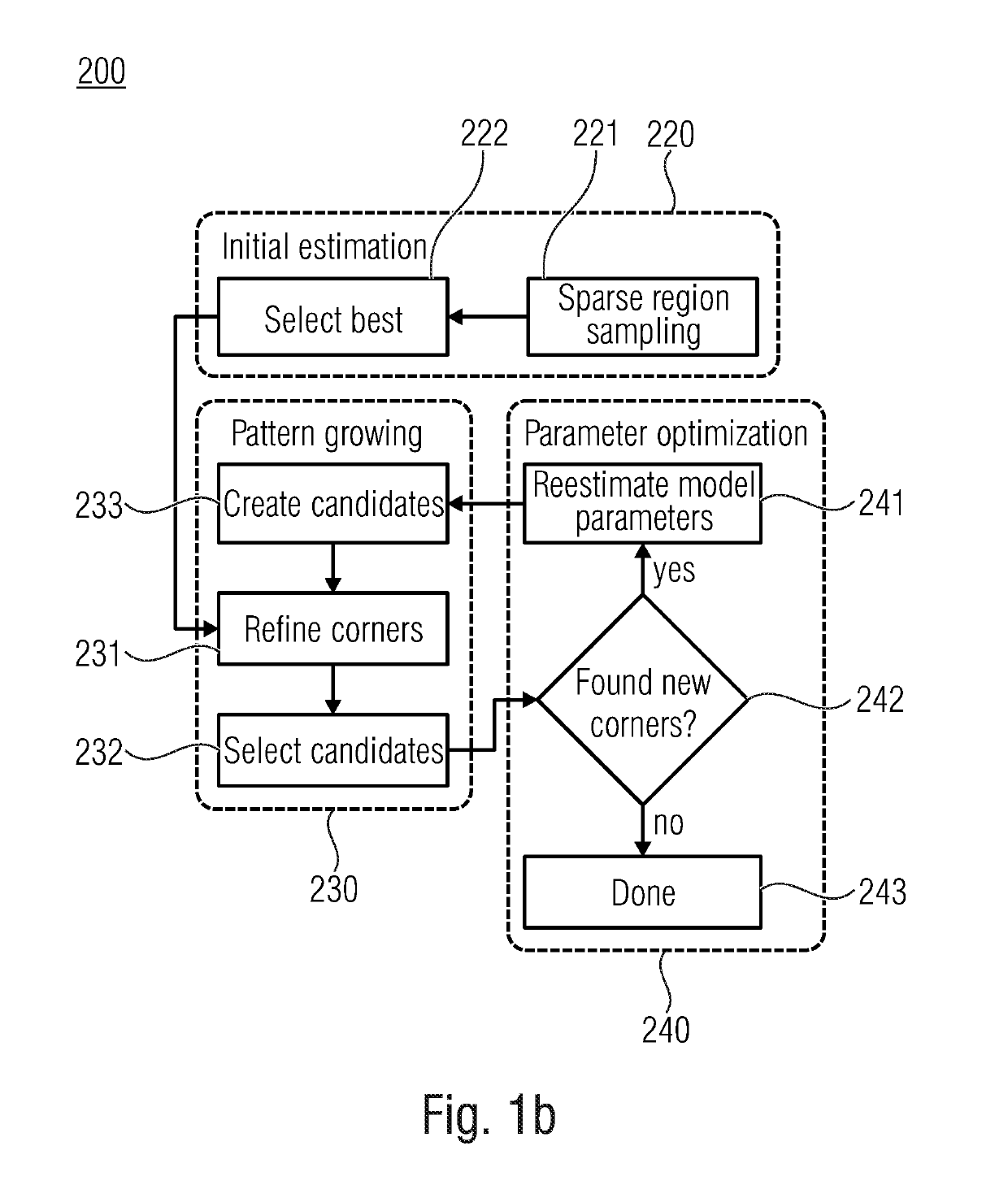
[0052]In the first step 110, a picture of the entire pattern 10 or a portion of the pattern 10 is taken. Starting from this picture, the pattern detection is performed usin...


PUM


Abstract

A method for detecting a known pattern having homogeneous areas includes the steps of taking an image of the known pattern or, of at least a portion of the known pattern, and performing detection. Detection includes an initial detection of a first region of the image and the detection of a feature of the known pattern within a second region of the image. The second region is arranged adjacent to the first region. The initial detection is aimed at estimating at least one region parameter, such as a position of the region of the pattern, and / or orientation of the region or distortion of same. Starting from this, the second region can be selected in which a feature, such as a corner of the checkerboard is detectable. This second detection step is aimed at obtaining at least one region parameter such as the position of a feature within the second region.

Description

CROSS-REFERENCES TO RELATED APPLICATIONS[0001]This application is a continuation of copending International Application No. PCT / EP2016 / 071724, filed Sep. 14, 2016, which is incorporated herein by reference in its entirety.[0002]Embodiments of the present invention refer to a method and an apparatus for detecting a known pattern having homogenous areas. Advantageous embodiments refer to robust chessboard detection for a geometric camera calibration.BACKGROUND OF THE INVENTION[0003]Nearly every camera and especially cameras having a wide viewing angle have to be calibrated. Such wide viewing angle cameras are often used for endoscopes.[0004]Endoscopic procedures are common clinical practice for a variety of diseases. Among others, minimally invasive surgery with endoscopic instruments is performed on abdominal organs (laparoscopy), joints (arthroscopy), or the brain (neurosurgery). Endoscopy involves good orientation, coordination, and fine motor skills of the surgeon. Therefore, comp...

Claims


Application Information

Patent Timeline
IPC IPC(8): G06K9/00G06T7/13G06T7/155G06T7/80G06T7/00
CPCG06T7/155G06K9/00503G06T7/97G06T2207/20036G06T7/80G06T7/13G06F2218/02
Inventor ERNST, ANDREASHOFFMANN, MATHISGARBAS, JENS-UWEBERGEN, TOBIAS
Owner FRAUNHOFER GESELLSCHAFT ZUR FOERDERUNG DER ANGEWANDTEN FORSCHUNG EV
Learn More