Electronic component

Active Publication Date: 2019-07-04
MURATA MFG CO LTD
View PDF6 Cites 0 Cited by
  • Summary
  • Abstract
  • Description
  • Claims
  • Application Information

AI Technical Summary

Benefits of technology

The present invention aims to provide an electronic component that generates fewer cracks. This means that the component is designed to be more durable and resistant to damage, which can ultimately save money and improve reliability.

Problems solved by technology

The conventional capacitor component mentioned above has the problem of causing the insulating layer and the electrode terminals to be cracked, for example, when stress is applied when the substrate bends.

Method used


Image

  • Electronic component
  • Electronic component
  • Electronic component

Examples


first embodiment

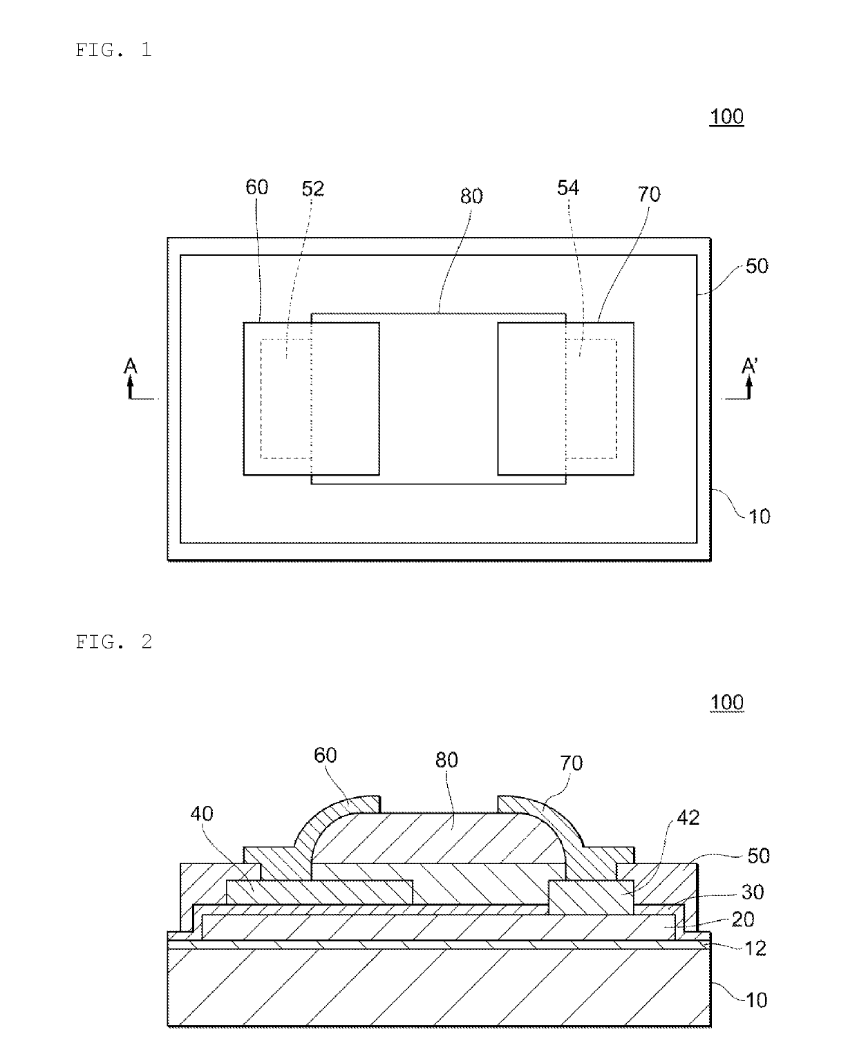
[0023]FIG. 1 is a plan view schematically illustrating the structure of a capacitor 100 according to the present invention. In addition, FIG. 2 is a diagram illustrating a cross section taken along line AA′ of FIG. 1. It is to be noted that FIGS. 1 and 2 illustrate an exemplary configuration for at least partially explaining features of the structure of the capacitor 100, but the capacitor 100 is not to be limited by the exact structure shown in the figures.

[0024]The capacitor 100 (which is an example of an electronic component) is configured to include a substrate 10, an insulating film 12, a lower electrode 20, a dielectric film 30, and an upper electrode 40. According to the present embodiment, the lower electrode 20, the dielectric film 30, and the upper electrode 40 constitute a capacitive element (which is an example of an element). In addition, the capacitor 100 includes a via electrode 42 (which is an example of a contact electrode) electrically connected to the lower electr...

second embodiment

[0056]FIG. 7 is a plan view schematically illustrating the structure of a capacitor 100 according to the present invention. In addition, FIG. 8 is a diagram illustrating a cross section taken along line AA′ of FIG. 5. It is to be noted that FIGS. 7 and 8 illustrate yet a further exemplary configuration required for at least partially explaining features of the structure of the capacitor 100, but the capacitor 100 is not limited by the exact structure shown in the figures.

[0057]For the capacitor 100 according to the present embodiment, terminal electrodes 60 and 70 have a two-layer structure. Specifically, the terminal electrode 60 includes a first layer 60-1 formed from an upper electrode 40 to a part of an insulating film 50, and a second layer 60-2 formed from the first layer 60-1 to a protective film 80. Likewise, the terminal electrode 70 includes a first layer 70-1 formed from a via electrode 42 to a part of the insulating film 50, and a second layer 70-2 formed from the first ...


PUM

PropertyMeasurementUnit
Dielectric polarization enthalpyaaaaaaaaaa
Elastic modulusaaaaaaaaaa

Abstract

An electronic component that includes a substrate having a first main surface and a second main surface, an element on the first main surface of the substrate, a first contact electrode electrically connected to the element, an insulating film defining a first opening at a position that has an overlap with the first contact electrode in the plan view of the first main surface, a protective film covering the insulating film in a region including at least a part of the periphery of the first opening, and a first external electrode electrically connected to the first contact electrode and extending over the protective film.

Description

CROSS REFERENCE TO RELATED APPLICATIONS[0001]The present application is a continuation of International application No. PCT / JP2017 / 039170, filed Oct. 30, 2017 which claims priority to Japanese Patent Application No. 2016-218406, filed Nov. 8, 2016, the entire contents of each of which are incorporated herein by reference.FIELD OF THE INVENTION[0002]The present invention relates to an electronic component.BACKGROUND OF THE INVENTION[0003]Conventional capacitor components include the capacitor component disclosed in Japanese Patent Application Laid-Open No. 5-47586 (Patent Document 1). The conventional capacitor component is provided with an insulating layer and two electrode terminals provided thereon, and mounted on a circuit board with the use of solder.[0004]Patent Document 1: Japanese Patent Application Laid-Open No. 5-47586SUMMARY OF THE INVENTION[0005]The conventional capacitor component mentioned above has the problem of causing the insulating layer and the electrode terminals...

Claims


Application Information

Patent Timeline
IPC IPC(8): H01G4/248H01G4/06H01G4/005H05K1/18
CPCH01G4/248H01G4/06H01G4/005H05K1/181H05K2201/10015H01G4/33H05K3/3431H01G4/252H01G4/012H01G2/10H01G4/224Y02P70/50H01G4/12H05K1/11H05K1/162
Inventor HAYASHI, YASUNOBUISHIDA, NOBUHIRO
Owner MURATA MFG CO LTD
Why Eureka
Try Eureka