
Film forming unit for sputtering apparatus

a technology of sputtering apparatus and forming unit, which is applied in the direction of vacuum evaporation coating, electric discharge tube, coating, etc., can solve the problems of complex apparatus arrangement and inconvenience in maintenance, and achieve the effect of improving the use efficiency of targets, simple constitution and improving function

Active Publication Date: 2019-07-04
ULVAC INC
View PDF0 Cites 0 Cited by
  • Summary
  • Abstract
  • Description
  • Claims
  • Application Information

AI Technical Summary

Benefits of technology

The invention provides a way to improve the efficiency of eroding targets in a sputtering process by using magnet units to evade local erosion and a driving mechanism to move the magnet units between an origin position and a turning position. This allows the targets to be eroded substantially uniformly over the entire surface and can be performed during film formation. The invention also suggests ways to minimize the volume of the evacuated chamber and simplifies the process of charging electric power to the targets.

Problems solved by technology

In the above-mentioned prior art, however, since the enclosure of the film forming unit is directly mounted on the inner wall surface of the vacuum chamber, there are problems in that the mounting and dismounting of the film forming unit are troublesome, resulting in inconvenience in maintenance.
For that purpose, it is necessary to separately provide the wall surface of the vacuum chamber with water supply pipes and water distributing pipes separately, thereby resulting in complex apparatus arrangement.

Method used


Image

  • Film forming unit for sputtering apparatus
  • Film forming unit for sputtering apparatus
  • Film forming unit for sputtering apparatus

Examples


Embodiment Construction

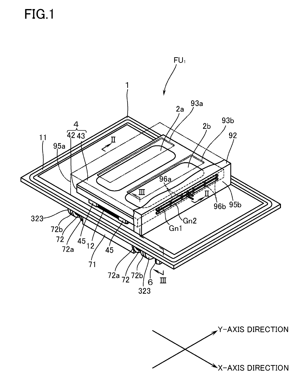
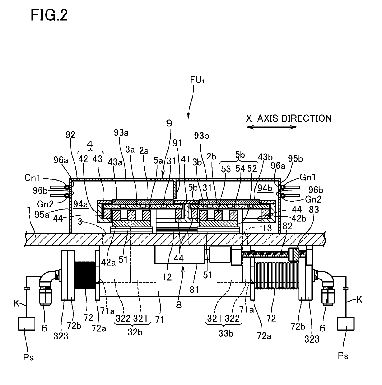
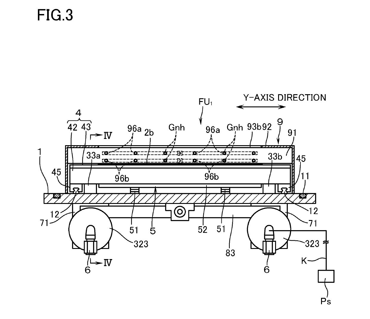
[0020]With reference to the drawings, a description will now be made of a first embodiment of a film forming unit for a magnetron sputtering apparatus according to this invention. In the following, it is to be understood that the film forming unit is attached to, or detached from, an opening in a vacuum chamber (not illustrated) in a posture shown in FIG. 1 of a film forming unit FU1, and the terms showing the direction such as “upper / top”, “lower / bottom” and the like shall be based on the posture in question. Further, the direction in which the target moves back and forth (reciprocates) at a certain stroke relative to the magnet unit is defined as an X-axis direction, and the longitudinal direction of the target perpendicular to the X-axis direction is defined as a Y-axis direction.

[0021]With reference to FIGS. 1 to 4, reference mark FU1 denotes a film forming unit for the magnetron sputtering apparatus according to the embodiment of this invention. The film forming unit is provide...


PUM

PropertyMeasurementUnit
magneticaaaaaaaaaa
electric poweraaaaaaaaaa
magnetic fieldaaaaaaaaaa

Abstract

In a film forming unit (FU) for a sputtering apparatus according to this invention, a supporting plate is provided with: a target having bonded thereto a backing plate; a magnet unit; and driving device for reciprocating the target along the supporting plate relative to the magnet unit. The backing plate is provided, in a protruded manner, with a supply pipe and a discharge pipe in communication with a coolant passage for the backing plate. A slit hole, which is elongated in the reciprocating direction of the target and through which the supply pipe and the discharge pipe penetrate, is formed in the supporting plate. The supporting plate has on its lower surface a cap body which hermetically encloses those portions of the supply pipe and the discharge pipe, inclusive of the slit hole, which are protruded downward from the slit hole.

Description

TECHNICAL FIELD[0001]The present invention relates to a film forming unit for a sputtering apparatus and, more particularly, relates to a film forming unit for a magnetron sputtering apparatus in which a target is arranged to reciprocate relative to a magnet unit.BACKGROUND ART[0002]This kind of film forming unit for a sputtering apparatus is known, e.g., in Patent Document 1. The unit in question is provided with a box-shaped enclosure (displacement part) which is mounted on an inner wall surface of a vacuum chamber in which film forming is performed, and a displacement plate is disposed on that side surface of the enclosure which looks inward of the vacuum chamber. The displacement plate has fixed thereto, through a supporting body, a backing plate which has a target bonded to one surface as a cathode. Further, positioned on the inside of an opening which is provided in the displacement plate, a magnet unit for causing to function a leakage magnetic field on the surface of the tar...

Claims


Application Information

Patent Timeline
Patent Type & Authority Applications(United States)
IPC IPC(8): H01J37/34
CPCH01J37/3435H01J37/3417H01J37/3497H01J37/345C23C14/3407C23C14/352H01J37/3455C23C14/35C23C14/34
Inventor SAITOU, SHUUJI
Owner ULVAC INC
Learn More