Structure of power carpentry feeder machine

a feeder machine and power technology, applied in the field of woodworking machines, can solve the problems of not having sound and stable structure, not having high precision generally, and high risk and physical burden on the operator, so as to ensure the smoothness and security of material feeding.

Active Publication Date: 2019-07-11
YU BEN
View PDF0 Cites 7 Cited by
  • Summary
  • Abstract
  • Description
  • Claims
  • Application Information

AI Technical Summary

Benefits of technology

[0004]In view of the above, in order to improve the prior art to alleviate or remove the problems of a known feeding machine of carpentry machinery being not structurally stable and being of a narrow scope of application, the present invention provides an improved structure of a power carpentry feeder machine, which generally comprises: a power source, which supplies rotation power; a rotary wheel, which is coupled to the power source to be in operation in combination therewith; two horizontal guide rods, are arranged in a manner of being spaced from each other to couple horizontally to the power base; a horizontal movement unit, which comprises two movable blocks, two locking members, a connection block, and two jointing members, each of the movable blocks being provided with a horizontal guide hole penetrating therethrough, the horizontal guide holes of the movable blocks respectively receiving insertion and extension of the horizontal guide rods therethrough respectively, the two locking members being respectively and operatively attached to the movable blocks, the connection block being interposed between the two movable blocks, the connection block comprising two vertical guide holes penetrating therethrough, the two jointing members being respectively coupled to and jointing between the movable blocks and the connection block; a mounting base, which comprises a base board and two vertical guide rods, the two vertical guide rods being arranged in a manner of being spaced from each other to vertically couple to a top surface of the base board and extending, in a direction

Problems solved by technology

Such an operation is generally carried out by human power and is thus not of high precision generally.
This is of high risk and a large physical burden to the operator.
However, such woodw

Method used


Image

  • Structure of power carpentry feeder machine
  • Structure of power carpentry feeder machine
  • Structure of power carpentry feeder machine

Examples


Embodiment Construction

[0014]The following descriptions are exemplary embodiments only, and are not intended to limit the scope, applicability or configuration of the invention in any way. Rather, the following description provides a convenient illustration for implementing exemplary embodiments of the invention. Various changes to the described embodiments may be made in the function and arrangement of the elements described without departing from the scope of the invention as set forth in the appended claims.

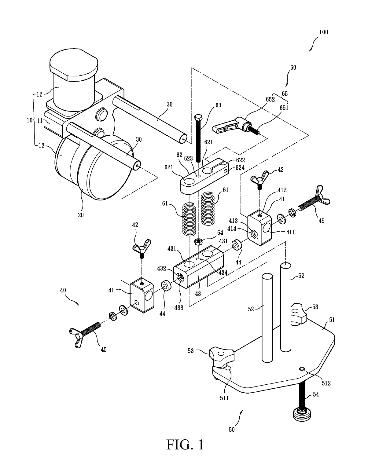
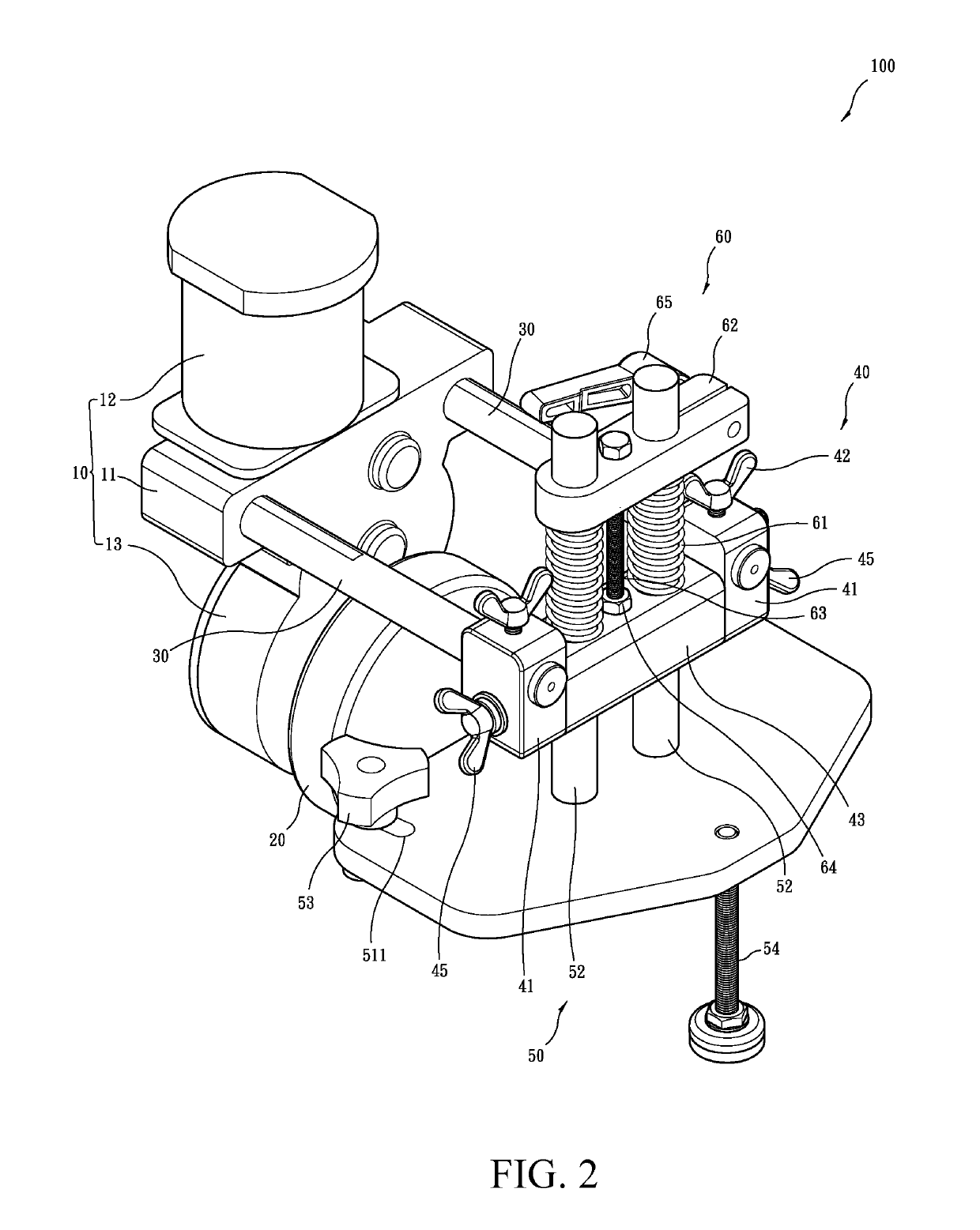
[0015]Referring to FIGS. 1-12, a power carpentry feeder machine 100 according to a preferred embodiment of the present invention is shown, generally comprising a power source 10, a rotary wheel 20, two horizontal guide rods 30, a horizontal movement unit 40, a mounting base 50, and a vertical movement unit 60.

[0016]Referring to FIGS. 1 and 2, the power source 10 comprises a power base 11, a motor 12, and a gearbox 13. The motor 12 is mounted on the power base 11 to supply an output of rotation power...


PUM


Abstract

A power carpentry feeder machine includes a power source; a rotary wheel operatively coupled to the power source; horizontal guide rods horizontally coupled to the power source; a horizontal movement unit including two movable blocks having horizontal guide holes to receive the horizontal guide rods therein, locking members attached to the movable blocks, a connection block interposed between the two movable blocks and including vertical guide holes, and jointing members jointing the movable blocks to the connection block; a mounting base including a base board and vertical guide rods vertically coupled to the base board and extending through the vertical guide holes; and a vertical movement unit including springs encompassing the vertical guide rods to set the connection block under the springs and a clamp block having clamping holes to receive the vertical guide rods to extend therethrough so as to set the clamp block on the springs.

Description

(a) TECHNICAL FIELD OF THE INVENTION[0001]The present invention generally relates to the field of woodworking machines, and more particularly to an improved structure of a power carpentry feeder machine.(b) DESCRIPTION OF THE PRIOR ART[0002]Common woodworking machines are circular saw machines and wood planing machine. Such woodworking machines are generally operated to cut timber or for surface finishing of wood parts. The operation is generally conducted by placing a timber or a wood part on the woodworking machines and holding the timber or wood part tightly on a slidable or movable feeder plate and a user applies a force to the feeder plate such that the feeder plate carries the timber or wood part forward for feeding. Such an operation is generally carried out by human power and is thus not of high precision generally. In addition, the operator must push or pull the timber or wood part placed on the woodworking machines in order to feed the timber or wood part forward. This is ...

Claims


Application Information

Patent Timeline
IPC IPC(8): B27C1/12
CPCB27C1/12B27B25/02B27B25/08B27C5/02B27C5/04B27C5/08B27C5/06B23Q7/055B23Q3/002
Inventor YU, BEN
Owner YU BEN
Why Eureka
Try Eureka